


Page 52
Wiring the Velocity-Only Sensor
Section 2
Note: The velocity-only probe and
the submerged AV probe cannot be
connected at the same time.
Disconnect all bare lead
connections or submerged AV
quick-connect connections to TB11
before connecting a velocity-only
bare lead connection. To prevent
dangling wires from touching the
circuit nodes, tape each individual
wire then bundle the wires and tape
them together.
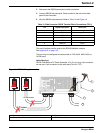
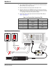
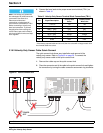
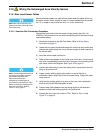
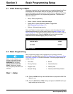
4. Connect the bare leads to the proper screw terminal block (TB11) as
shown in Tabl e 15.
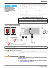
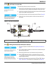
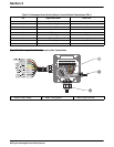
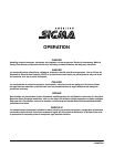
2.18.2 Velocity-Only Sensor Cable Quick-Connect
The quick-connect hub allows easy installation and removal of the
velocity-only sensor. Refer to Figure 25 on page 52. To connect the
velocity-only sensor cable to the quick-connect hub:
1. Remove the rubber cap on the quick-connect hub.
2. Place the connector-end of the cable to the quick-connect hub and tighten
the connection by turning the cable connector securement ring clockwise.
Figure 25 Quick-Connect Hub
Table 15 Velocity-Only Sensor Terminal Block Connections (TB11)
Pin Signal Description
Factory Wire
Color*
* If the factory prepared cable end is cut off, the wire colors will no longer match. Use
the trimmed cable wire colors.
Trimmed Cable
Wire Color
10 + 12 V dc red red
11 common green green
12 XMIT + (pos) gray gray
13 XMIT - (neg) violet violet
14 RCV + (pos) orange orange
15 RCV - (neg) yellow b/w shield
16 shield clear clear
1. Quick-connect Hub
J12
J13
TB8
XMIT+
CH A+CH 4
RAIN+
1
1
1
XMIT–
RCV+
RCV–
SHEILD
AVTB11
TB10 4-20 mA
TB 9 ANALOG
TB4
RAIN
COMMON
CH A–COMMONRAIN–
+12V
SHIELDSHIELDSHIELD
DEPTH–
CH B+CH 5CH 1
DEPTH+
CH B–COMMONCOMMON
SHIELD
SHIELDSHIELDSHIELD
COMMON
STARTCH 6CH 2
DSR
PULSECOMMONCOMMON
RXD
BOTTLESHIELDSHIELD
SHIELD
SHIELD
TOTALIZER
TB7
TB6
TB2
TB5
TOTAL –
RTD –
TIP
TIP
TOTAL +
1
1
MODEM
ULTRASONIC
RTD
RING
RING
RTD
DTR
EVENTCH 7CH 3
TXD
COMMONCOMMONCOMMON
+12V
SHIELDSHIELDSHIELD
RS232C
SAMPLERANALOGANALOG
1
1
1
1
2
2
2
2
3
3
3
3
4
4
4
4
5
5
5
5
6
6
6
6
7
7
7
7
8
8
8
8
9
9
9
9
10
10
10
10
11
11
11
11
12
12
12
12
13 14 15 16
SHIELD
TB3
pH
REF
pH
RTD
–5V
COMMON
+5V
485A
485B
485+NO
NO
NO
NO
485GNDCOM RELAY 1
COM RELAY 2
COM RELAY 3
COM RELAY 4
SHIELDNC
NC
NC
NC
RS485
1 2 3 4 5 6 7 8 9 10 1112
F2
F1
HOT/ 1
NEU/ 2
T, 1.0A 250V
ON
HOT/ 1
NEU/ 2
TB8
1
4
7
10
2
5
8
11
3
6
9
12
J13
1
POWER
OFF
No Connection