


Page 44
Wiring the RS232
Section 2
2.13 Wiring the RS232
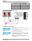
Note: Do not connect the RS232
port to more than one external
device at the same time. Connecting
an external device to both the side
panel quick-connect fitting and the
terminal circuit board inside the 980
Flow Meter can cause instrument
failure and unreliable
communications.
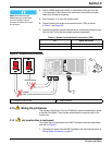
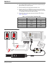
The quick-connect RS-232 connector is located on the side panel of the
980 Flow Meter housing. The RS232 is intended for temporary connection
between a PC and 980 Flow Meter using a serial interface cable
(Cat. No. 1727) or a DTU-II. The 980 Flow Meter also allows for a permanent
connection that is routed by an external communications cable to the
980 Flow Meter through a conduit opening.
Permanent Conduit Connection
1. With power to the controller off, use a large flat-blade screwdriver to
loosen the two screws securing the 980 Flow Meter cover. Open the
cover. See Wiring Safety Information on page 31.
Note: To minimize electromagnetic
affects on the 980 Flow Meter
performance shielded cable is
required. To ensure that ground
currents in inadequate ground
systems do not result in potential
shock hazards do not connect the
shields at both ends of the cable.
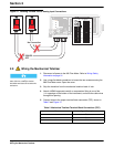
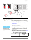
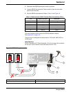
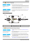
2. Disconnect the RS232 Quick-connect attached to the TB11 pins.
No wires should remain in the socket.
3. To prevent dangling wires from touching the circuit nodes, tape each
individual wire then bundle the wires and tape wires together.
See Figure 19.
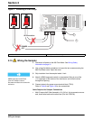
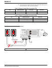
4. Attach a NEMA-approved conduit or compression fitting to one of the
½ in. openings on the bottom of the instrument, and route the RS232
permanent connection 6-wire cable and five conductors with shield.
5. Strip the outer insulated jacket back 2 inches from the end of the RS232
cable. Use care when removing the outer jacket to ensure that the
insulation around the inner conductors is not nicked. Nicked insulation on
inner conductors can lead to shorting.
Note: Route wires through
NEMA-approved conduit hubs
(Cat. No. 16483) to ensure
that water and dust do not enter the
enclosure.
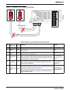
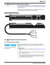
6. Strip insulation of the individual wires back ¼ inch.
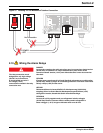
7. Connect each bare wire end to the proper screw terminal block (TB11).
Refer to Table 9 and Figure 19. Do not leave any of the bare wire
exposed.
8. Connect the cable shield to protective earth (ground) at the 980 Flow
Meter. Do not connect the cable shield at the remote end of the cable. Cut
the cable jacket back far enough to expose the conductors and remove
the shield by cutting it even with the cable jacket. Insulate the remaining
exposed shield with tape or heat shrink tubing.
Reconnecting the RS232 Quick-Connect
1. With the power to the controller off, use a flat-blade screwdriver to loosen
the two screws securing the 980 Flow Meter cover.
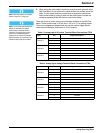
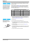
Table 9 Conduit RS232 Terminal Block Connections (TB11)
Pin Signal Description
2TXD
3DTR
4RXD
5DSR
6 common
7shield