


Section 5
Page 103
Memory Batteries
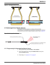
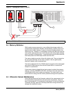
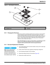
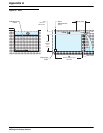
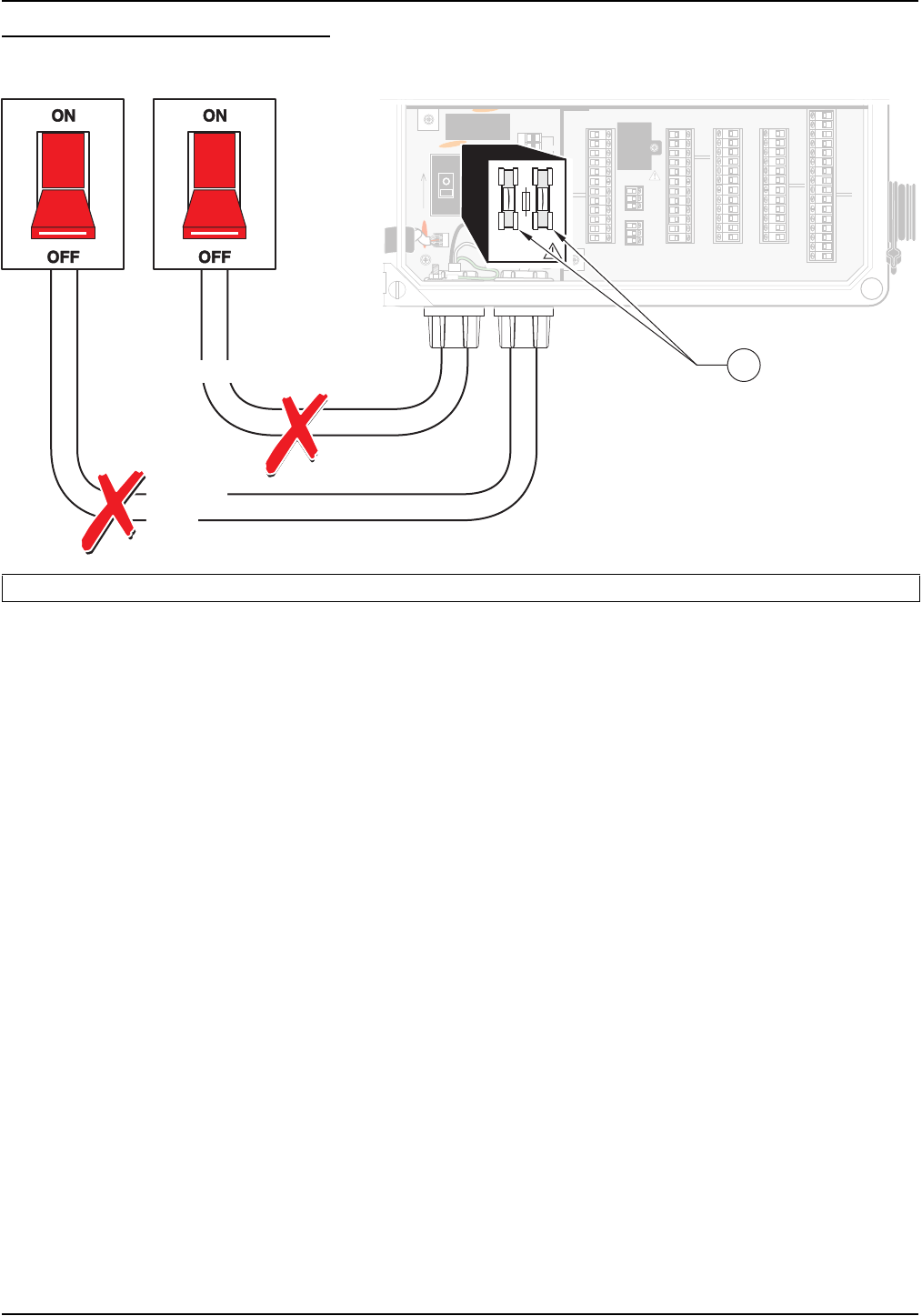
Figure 46 Locating the Fuses (F1 and F2)
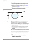
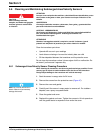
5.4 Memory Batteries
RAM (random access memory) is a very reliable data storage medium for
microprocessor applications. Random Access Memory requires power at all
times to store its data, however. If power is removed, the data stored in the
RAM chip is lost. Therefore, it is not feasible to power the RAM chips from the
meter power supply because you would lose your data and program settings
every time power is disconnected. A separate battery pack located inside the
flow meter powers the RAM chips and the real time clock.
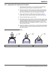
The memory batteries consist of three AA alkaline cells. They are located on
the rear panel assembly and are easy to replace. Use only good quality
alkaline AA battery cells as replacements.
The memory batteries (Cat. No. SE 989) keep the program entries and logged
data stored in RAM memory when the main power fails or is removed for
transport or replacement.
If the memory battery voltage falls too low to properly maintain the program
settings, a warning: “MEMORY BATTERY” will flash in the lower right corner
of the display to alert you to replace the batteries. The meter uses a very
small amount of energy from the memory batteries during normal operation.
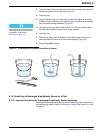
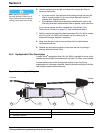
5.5 Ultrasonic Sensor Maintenance
One of the key features of the Ultrasonic method of flow measurement is the
low maintenance requirements for the level sensor (transducer). Clean the
face of the transducer if it is coated by dirt and grease. To clean the Ultrasonic
Transducer housing, wipe with a mild soap and water. Strong solvents may
damage the transducer housing.
1. F1 and F2 (T, 1A, 250V)
J12
J13
TB8
XMIT+
CH A+CH 4
RAIN+
1
1
1
XMIT–
RCV+
RCV–
SHEILD
AVTB11
TB10 4-20 mA
TB 9 ANALOG
TB4
RAIN
COMMON
CH A–GROUNDRAIN–
+12V
SHIELDSHIELDSHIELD
DEPTH–
CH B+CH 5CH 1
DEPTH+
CH B–GROUNDGROUND
SHIELD
SHIELDSHIELDSHIELD
COMMON
STARTCH 6CH 2
DSR
PULSEGROUNDGROUND
RXD
BOTTLESHIELDSHIELD
SHIELD
SHIELD
TOTALIZER
TB7
TB6
TB2
TB5
TOTAL –
RTD –
TIP
TIP
TOTAL +
1
1
MODEM
ULTRASONIC
RTD
RING
RING
RTD
DTR
EVENTCH 7CH 3
TXD
GROUNDGROUNDGROUND
+12V
SHIELDSHIELDSHIELD
RS232C
SAMPLERANALOGANALOG
1
1
1
1
2
2
2
2
3
3
3
3
4
4
4
4
5
5
5
5
6
6
6
6
7
7
7
7
8
8
8
8
9
9
9
9
10
10
10
10
11
11
11
11
12
12
12
12
13 14 15 16
SHIELD
TB3
pH
REF
pH
RTD
–5V
GROUND
+5V
485A
485B
485+NO
NO
NO
NO
485GNDCOM RELAY 1
COM RELAY 2
COM RELAY 3
COM RELAY 4
SHIELDNC
NC
NC
NC
RS485
123456789101112
F2
F1
HOT/ 1
NEU/ 2
T, 1.0A 250V
ON
HOT/ 1
NEU/ 2
TB8
1
4
7
10
2
5
8
11
3
6
9
12
J13
F2
F1
T, 1.0A 250V
No Connection
POWER
OFF
1