


Section 2
Page 41
Wiring the Rain Gauge
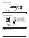
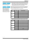
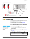
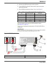
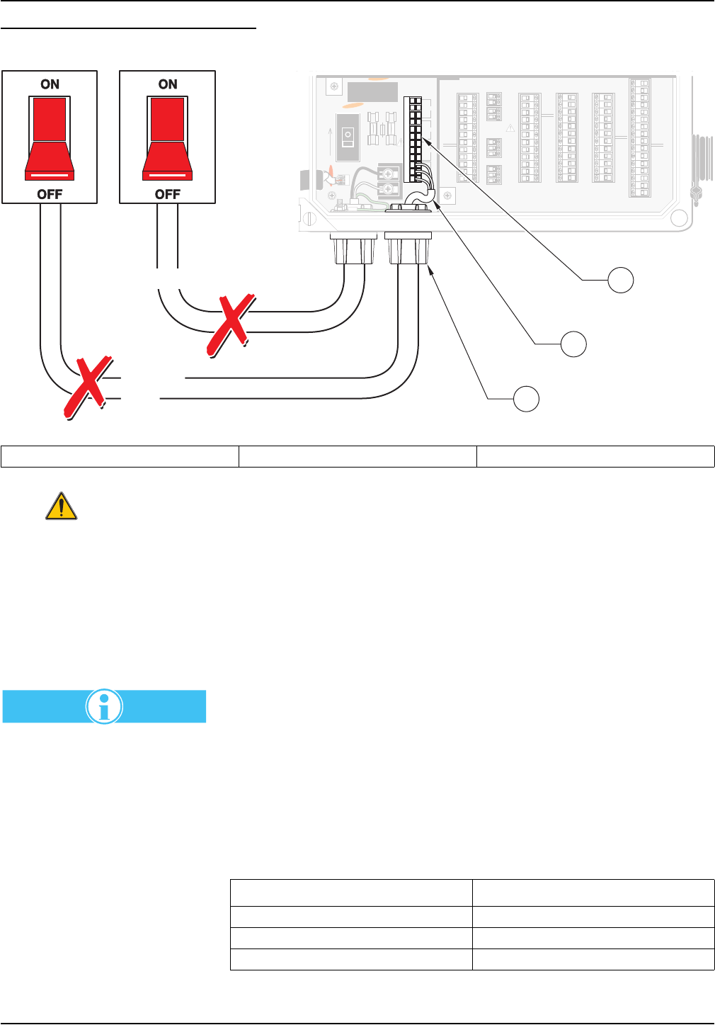
Figure 16 Locating TB13 for Alarm Relay Connection
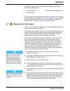
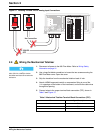
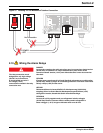
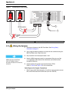
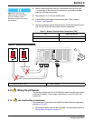
2.11 Wiring the Rain Gauge
An external “tipping bucket” rain gauge (such as Cat. No. 9708400) can be
connected to the rain gauge connector of the 980 Flow Meter. The rain gauge
provides a dry contact closure to the flow meter.
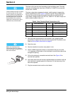
1. Disconnect all power to the 980 Flow Meter. See Wiring Safety
Information on page 31.
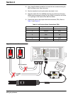
2. Use a large flat-blade screwdriver to loosen the two screws securing the
980 Flow Meter cover. Open the cover.
3. Strip insulation from the rain gauge leads ¼ inch.
Note: Route wires through
NEMA-approved conduit hubs
(Cat. No. 16483) to ensure
that water and dust do not enter the
enclosure.
4. Attach a NEMA-approved conduit or compression fitting to one of the
½ in. openings on the bottom of the instrument, and route the wires
through this opening.
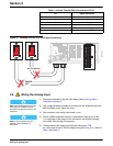
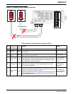
5. Connect wires to the proper screw terminal block (TB4). Refer to Table 7
and Figure 17.
1. Appropriate strain relief, or seal. 2. One relay connection shown. 3. J13, 12-pin terminal block
J12
J13
TB8
XMIT+
CH A+CH 4
RAIN+
1
1
1
XMIT–
RCV+
RCV–
SHEILD
AVTB11
TB10 4-20 mA
TB 9 ANALOG
TB4
RAIN
COMMON
CH A–GROUNDRAIN–
+12V
SHIELDSHIELDSHIELD
DEPTH–
CH B+CH 5CH 1
DEPTH+
CH B–GROUNDGROUND
SHIELD
SHIELDSHIELDSHIELD
COMMON
STARTCH 6CH 2
DSR
PULSEGROUNDGROUND
RXD
BOTTLESHIELDSHIELD
SHIELD
SHIELD
TOTALIZER
TB7
TB6
TB2
TB5
TOTAL –
RTD –
TIP
TIP
TOTAL +
1
1
MODEM
ULTRASONIC
RTD
RING
RING
RTD
DTR
EVENTCH 7CH 3
TXD
GROUNDGROUNDGROUND
+12V
SHIELDSHIELDSHIELD
RS232C
SAMPLERANALOGANALOG
1
1
1
1
2
2
2
2
3
3
3
3
4
4
4
4
5
5
5
5
6
6
6
6
7
7
7
7
8
8
8
8
9
9
9
9
10
10
10
10
11
11
11
11
12
12
12
12
13 14 15 16
SHIELD
TB3
pH
REF
pH
RTD
–5V
GROUND
+5V
485A
485B
485+NO
NO
NO
NO
485GNDCOM RELAY 1
COM RELAY 2
COM RELAY 3
COM RELAY 4
SHIELDNC
NC
NC
NC
RS485
123456789101112
F2
F1
HOT/ 1
NEU/ 2
T, 1.0A 250V
ON
HOT/ 1
NEU/ 2
TB8
1
4
7
10
2
5
8
11
3
6
9
12
J13
POWER
OFF
No Connection
1
2
3
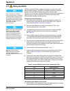
Table 7 Rain Gauge Terminal Block Connections (TB4)
Pin Signal Description
1 Rain + (pos)
2 Rain - (neg)
3Shield