


Section 2
Page 31
Wiring Safety Information
2.4 Wiring Safety Information
When making any wiring connections to the 980 Flow Meter, the following
warnings and notes must be adhered to, as well as, any warnings and notes
found throughout the individual installation sections. For more safety
information refer to Safety Precautions on page 8.
DANGER
Always disconnect power to the
instrument when making
electrical connections.
DANGER
Débranchez toujours l'alimentation électrique de l'instrument en établissant les
rapports électriques.
PELIGRO
Desconectar siempre las fuentes de energía del instrumento al hacer eléctrico
conectado.
GEFAHR
Vor Durchführung von Arbeiten an der Elektrik ist das Gerät unbedingt
spannunsfrei zu machen.
PERIGO
Scollegare sempre l’alimentazione elettrica quando rendono elettrico collegato.
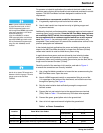
Electrostatic Discharge (ESD) Considerations
To minimize hazards and ESD
risks, maintenance procedures
not requiring power to the
analyzer should be performed
with power removed.
Delicate internal electronic components can be damaged by static electricity,
resulting in degraded instrument performance or eventual failure.
The manufacturer recommends taking the following steps to prevent ESD
damage to your instrument:
• Before touching any instrument electronic components (such as
printed circuit cards and the components on them) discharge static
electricity from your body. This can be accomplished by touching an
earth-grounded metal surface such as the chassis of an instrument,
or a metal conduit or pipe.
• To reduce static build-up, avoid excessive movement. Transport
static-sensitive components in anti-static containers or packaging.
• To discharge static electricity from your body and keep it discharged, wear
a wrist strap connected by a wire to earth ground.
• Handle all static-sensitive components in a static-safe area. If possible,
use anti-static floor pads and work bench pads.
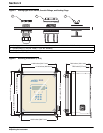
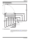
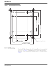
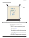
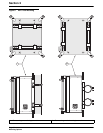
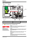
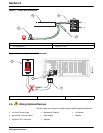
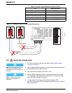
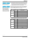
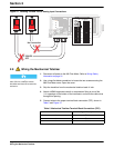
2.5 Wiring the Controller
The 980 Flow Meter is divided into two sections by a voltage isolation barrier.
The left side of the barrier contains the high voltage wiring and the right side
of the barrier contains the low voltage wiring. See Figure 10 for proper
placement of connectors.