


Page 133
SCADA-Modbus® System Guidelines
Appendix E SCADA-Modbus
®
System Guidelines
Introduction to SCADA - Modbus Communications
Use this section as a guide when using the Modbus ASCII protocol to
communicate directly with the 980 Flow Meter via an RS232 or modem
connection.
This guide assumes that the user has a working knowledge of Supervisory
Control and Data Acquisition (SCADA), its components, and the different
topologies used to construct the communications network. Because a basic
understanding of the Modbus ASCII protocol is necessary, a description of
key pieces of the protocol will be described.
This section will guide you through the setup process by describing key points
that need to be addressed for successful communication. This section will not
outline specific implementation details of any particular Man Machine
Interface (MMI) or controller, although examples may reference certain
manufacturers for illustrative purposes. The description of the Modbus ASCII
protocol is provided for reference only and is not intended as a tutorial. The
scope of this section is limited to the description of Modbus ASCII as it
pertains to the 980 Flow Meter.
Modbus, an open protocol, determines how each instrument will know its
device address, recognize a message addressed to it, determine the type of
action to be taken, and extract any data or other information contained in the
message. The flow meter and Man Machine Interface (MMI) communicate
using a master-slave technique in which only the master can initiate queries to
a slave (980). The 980 will always be considered the slave, never a master.
The master can address individual 980 Flow Meters or can broadcast a
message to instruments within its scope. Responses are never returned to
broadcast queries from the master. The Modbus protocol establishes the
format for the master’s query by placing into it the device address, a function
code defining the requested action, any data to be sent, and an error-
checking field. The flow meter’s response message is constructed using the
Modbus format which confirms the action to be taken, any data to be returned,
and an error checking field.
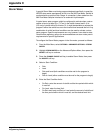
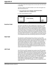
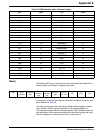
ASCII Transmission Mode
The 980 Flow Meter is designed to communicate on standard Modbus
networks using Modbus ASCII. In ASCII mode, messages start with a colon
‘:’, and end with a ‘carriage return-line feed’ pair. The allowable characters
transmitted for all fields are hexadecimal 0–9, and A–F. When a message is
transmitted over a Modbus ASCII communication link, each character or byte
is sent in the order of Least Significant Bit to Most Significant Bit. A typical
message frame looks like the following:
Address Field
The address field of an ASCII message frame, ranging from 0 to 247
decimals, consists of two characters that represent the slave address.
Individual slaves are assigned values between 1 and 247. A master
addresses a slave by putting the slave’s address in the address field of the
message frame. When the slave sends its response, it places its own address
START ADDRESS
(HEX)
FUNCTION
(HEX)
DATA
(HEX)
LRC
(HEX)
END
(HEX)
1 Char ‘:’ 2 Chars 2 Chars n Chars 2 Chars 2 Chars ‘CRLF’