


Appendix E
Page 135
SCADA-Modbus® System Guidelines
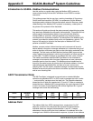
Communication Parameters
To successfully communicate with the 980 Flow Meter using Modbus ASCII,
the communication parameters of the master device must be set at 7 bits,
Even Parity, and 1 Stop bit. The baud rate may be configured to any value
offered by the 980 Flow Meter. With the exception of baud rate, the
communication parameters must not vary from this format.
User Memory Customizing
The most familiar component of existing SCADA networks today is the
Programmable Logic Controller (PLC). Because the network integrator is
most familiar with this type of device, the flow meter emulation of an existing
PLC simplifies the process of integrating the manufacture’s instrumentation
into the SCADA network. Modbus ASCII uses a referencing system to identify
the various types of memory inputs and outputs. Each reference number has
a leading digit that identifies its data type (discrete input, discrete output,
register input, register output) followed by a string of digits that indicates its
location in RAM (Table 33).
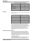
The memory data is stored in 16-bit words. Within the predefined function
codes of the Modbus ASCII protocol, the data fields are subject to
interpretation by the device manufacturer. For example, the 980 Flow Meter
places temperature information in registers 40001-40002.
Modbus ASCII Function Codes Supported
Currently, the 980 Flow Meter is capable of a read-only function to retrieve
channel and total flow information. All data addresses in the Modbus ASCII
message are referenced to zero. Therefore, a reference to holding register
40001 is addressed as register 0000. The function code field specifies the
type of register accessed; therefore, the 4XXXX is implicit.
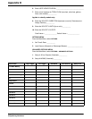
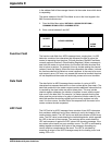
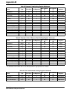
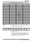
Function 03: Read Holding Registers
Reads the register (4X reference) contents of the 980 Flow Meter as defined
in the tables that follow.
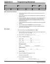
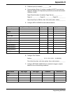
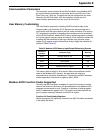
Table 33 Modbus ASCII Memory Input/Output Referencing System
Reference
Indicator
Reference Type Meaning
0xxxx discrete output or coil binary
1xxxx discrete input binary
3xxxx input register real
4xxxx output holding register real
6xxxx extended memory register real