


Section 2
Page 33
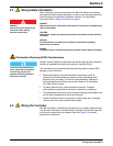
Wiring the Controller
For process or industrial applications, the national electrical codes of most
countries require that ac service feeds be hard-wired and contained in conduit
systems. The 980 Flow Meter has been designed to conform to this
requirement.
Note: If power cords are allowed
by local electrical code, a 125 V
UL/CSA–approved power cord
with an approved NEMA-style strain
relief and a standard 115 V North
American-style plug
(Cat. No. 4630600) or a 230 V
VDE-approved power cord with an
approved NEMA-style strain relief
and a Continental European-style
plug (Cat. No. 4630800) can be
ordered.
The manufacturer recommends conduit for two reasons:
1. It is generally required by most local electrical codes, and
2. Use of metal conduit can improve immunity to lightning surges and
ac power transients.
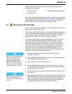
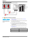
Additionally, electrical and instrumentation standards require a local means of
removing power from the product. Since the 980 Flow Meter does not have
an accessible ON/OFF switch, the customer must provide one. This may
be accomplished with a customer-supplied switch box or with a power
cord. See Figure 12. As previously stated, a power cord method is only
acceptable if local codes permit its use and the considerations outlined in the
previous paragraphs are addressed.
In hard-wired electrical applications the power and safety ground service
drops for the 980 Flow Meter should be no longer than 6 meters (20 feet)
unless metal conduit is used to shield the ac power wiring.
In applications where power cords are allowed by local electrical codes
and power surges and transients are not a great concern, an 18 gauge,
3-conductor power cord (including a safety ground wire) can be used, but its
length must not exceed 3 meters (10 feet).
Note: The field wiring terminal
barrier for ac power will accept wire
between 18 and 12 gauge. The wire
gauge must not be less than
18 AWG.
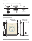
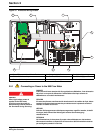
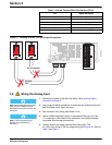
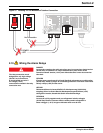
Carefully read all of the warnings in this section, and refer to Figure 11
to ensure the connections are correctly installed.
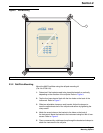
1. Use a large flat-blade screwdriver to loosen the two screws securing the
980 Flow Meter cover. Open the cover.
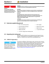
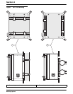
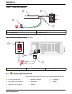
2. Attach a NEMA-approved conduit or compression fitting to one of the
½ in. openings on the bottom of the instrument, and route the ac wires
through this opening. See Figure 6.
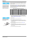
3. Strip the wire insulation back sufficiently enough to wrap around
terminal screws.
4. Connect the hot and neutral wires to the appropriate screw terminal
(TB 8). Refer to Table 1. Do not leave any of the bare wire exposed.
5. Connect the green, green/yellow wire to the ground stud.
6. Use a
5/16 inch open-end wrench to tighten the ground stud.
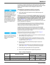
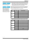
Table 1 ac Power Connections
Location Power Wire Color Codes
Circuit Board Marking
International U.S.A.
TB8 White (North America) Blue (International) ∅ 2
neutral
TB8 Black (North America) Brown (International) ∅ 1 hot
Conduit Plate Green (North America) or green/yellow (International) ground