Section 2
Page 49
Wiring the Downlook Ultrasonic Sensor
2.15.2 pH Probe to Junction Box
Note: pH sensor wire connections
are found inside the junction
box cover.
To connect the pH Sensor to the pH Junction Box:
1. Remove the four hold-down screws and nylon taper seals on the cover of
the pH junction box with a Phillips-head screwdriver. Remove the cover.
2. Loosen the compression fitting and route the pH sensor cable through the
fitting. Pull the cable into the junction box.
Note: Pull excess slack cable out of
the junction box and tighten the
compression fitting on the box.
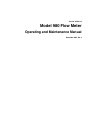
3. Connect the pH sensor wires to the screw terminals. Refer to Figure 22.
4. Replace the cover, the cover gasket, and the nylon taper seals on all
four screws.
Figure 22 pH Probe to Junction Box
2.16 Wiring the Downlook Ultrasonic Sensor
Note: To ensure protection against
electrical shock reinstall cover over
sensor terminal connection.
1. Disconnect all power to the 980. Refer to Wiring Safety Information on
page 31.
2. Use a large flat-blade screwdriver to loosen the two screws securing the
980 cover. Open the cover.
3. Remove the protective cover over the sensor terminal connection.
Note: Route wires through
NEMA-approved conduit hubs
(Cat. No. 16483) to ensure water
and dust do not enter the enclosure.
4. Attach a NEMA-approved conduit or compression fitting to one of the
½ in. openings on the bottom of the instrument, and route the ultrasonic
cable through the opening.
5. Install wires to the proper screw terminal block (TB5 and TB6). Refer to
Table 13 and Tabl e 14 for connection pin assignments and Figure 23.
1. Pre-wired strain relief 2. Compression Fitting
(NEMA-approved strain relief)
3. pH Probe Cable
3328 pH 0293 02
pH
SHLD
RTD
RTD
REF
GND
GLASS
21
3