


ENGINE
3.26
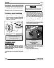
VALVE SEAT RECONDITIONING CONT’D
S If the contact area of the cutter is in
the same place, the valve guide is
distorted from improper installation.
S If the contact area of the initial cut is
greater than 75%, continue to cut the
seat until all pits are removed and a
new seat surface is evident. NOTE:
Remove only the amount of material
necessary to repair the seat surface.
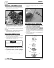
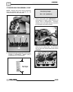
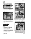
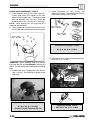
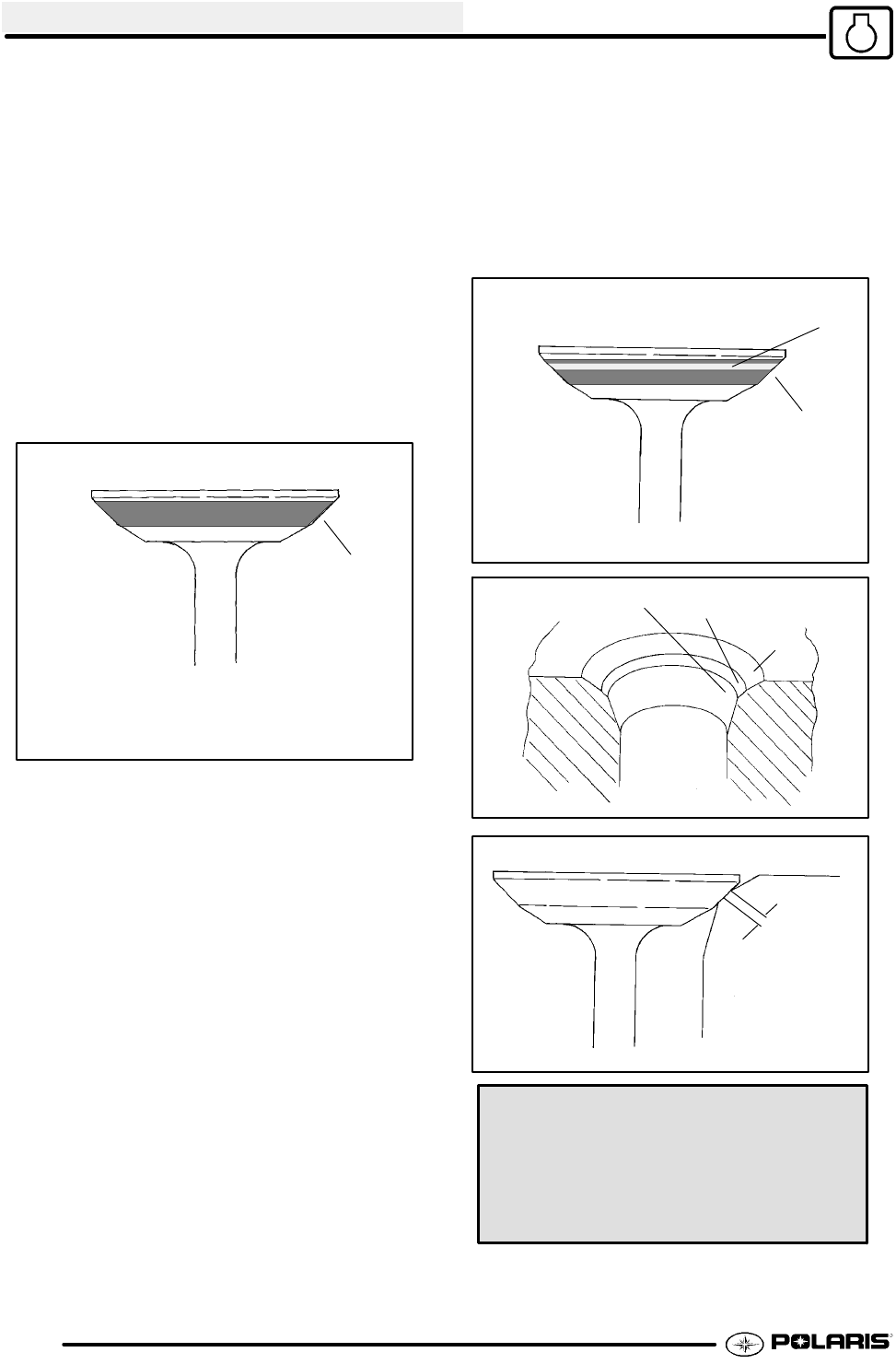
5. To check the contact area of the seat on the valve
face, apply a thin coating of Prussian Bluetpaste
to the valve seat. If using an interference angle
(46°) apply black permanent marker to the entire
valveface(A).
(A)
6. Insert valve into guide and tap valve lightly into
place a few times.
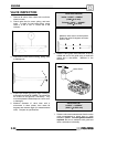
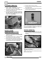
7. Remove valve and check where the Prussian
Bluet indicates seat contact on the valve face.
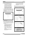
The valve seat should contact the middle of the
valve face or slightly above, and must be the
proper width.
S If the indicated seat contact is at the
top edge of the valve face and
contacts the margin area(B) it is too
high on the valve face. Use the 30°
cutter to lower the valve seat.
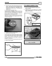
S If too low, use the 60° cutter to raise
the seat. When contact area is
centered on the valve face, measure
seat width.
S If the seat is too wide or uneven, use
both top and bottom cutters to
narrow the seat.
S If the seat is too narrow, widen using
the 45° cutter and re-check contact
point on the valve face andseat width
after each cut.
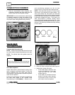
NOTE: When using an interference angle, the seat
contact point on the valve will be very narrow, and is
a normal condition. Look for an even and continuous
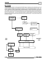
contact point all the way around the valve face. (B)
(A)
(B)
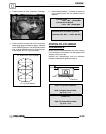
Proper Seat Contact On Valve Face
Bottom - 60°
Seat - 45°
Top - 30°
Seat
Width
Valve Seat Width:
Intake Std: .028I (.7 mm)
Limit: .055I (1.4 mm)
Exhaust Std: .039I (1.0 mm)
Limit: .071I (1.8 mm)