


ELECTRICAL
10.37
STARTER SYSTEM
TROUBLESHOOTING
Starter Motor Does Not Turn
G Battery discharged. Low specific
gravity
G Loose or faulty battery cables or
corroded connections (see Voltage
Drop Tests)
G Related wiring loose, disconnected,
or corroded
G Poor ground connections at battery
cable, starter motor or starter
solenoid (see Voltage Drop Tests)
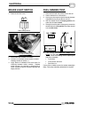
G Faulty key switch
G Faulty kill switch
G Faulty starter solenoid or starter
motor.
G Engine problem - seized or binding
(Can engine be rotated easily with
recoil starter?)
Starter Motor Turns Over Slowly
G Battery discharged - low specific
gravity
G Excessive circuit resistance - poor
connections (see Voltage Drop Test
below)
G Engine problem - seized or binding
(Can engine be rotated easily?)
G Faulty or worn brushes in starter
motor
Starter Motor Turns - Engine Does Not Rotate
G Faulty starter drive
G Faulty starter drive gears or starter
motor gear
G Faulty flywheel gear or loose
flywheel
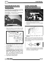
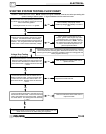
VOLTAGE DROP TEST
The Voltage Drop Test is used to test for bad
connections. When performing the test, you are
testing the amount of voltage drop through the
connection. A poor or corroded connection will
appear as a high voltage reading. Voltage shown on
the meter when testing connections should not
exceed .1 VDC per connection or component
.
To perform the test, place the meter on DC volts and
place the meter leads across the connection to be
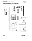
tested. Refer to the chart on 1.47 to perform voltage
drop tests on the starter system.
Voltage should not exceed
.1 DC volts per connection
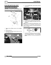
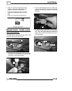
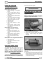
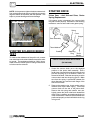
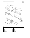
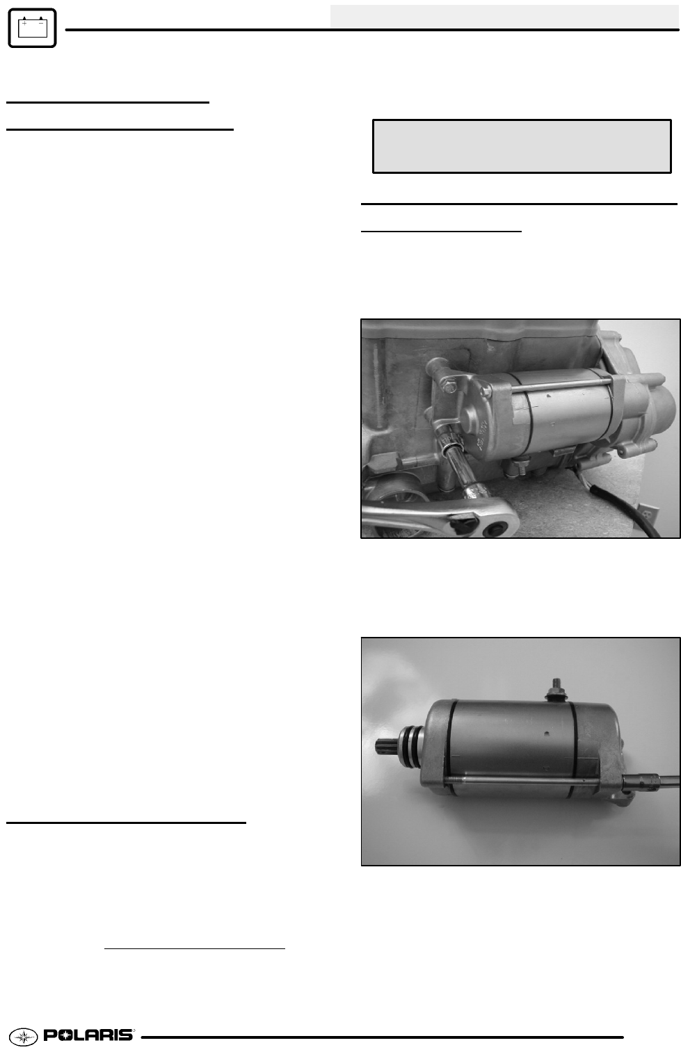
STARTER MOTOR REMOVAL/
DISASSEMBL
Y
NOTE: Use electrical contact cleaner to clean starter
motor parts. Some solvents may leave a residue or
damage internal parts and insulation.
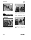
1. Remove the starter from the engine.
2. Remove the two bolts, washers, and sealing
O-Rings. Inspect O-Rings and replace if
damaged.
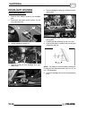
NOTE: Note the alignment marks on both ends of the
starter motor casing. These marks must align during
reassembly.
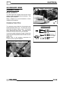
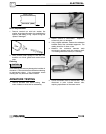
3. Remove the front bracket assembly and the rear
bracket assembly. Remove the shims from the
armature shaft and inspect the O--rings located
on the armature housing.