


CLUTCH
6.21
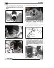
EBS DRIVEN CLUTCH
DISASSEMBLY/INSPECTION
-
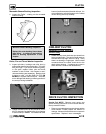
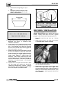
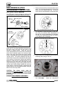
EBS Driven Clutch Operation
This EBS driven clutch provides the same engine
braking abilities as the earlier EBS driven clutch.
One--way Clutch
Drive Clutch
Belt Rotation
Downhill
Drive
Driven
When the ATV is moving downhill the drive train turns
the driven clutch, belt, and one way clutch in the
direction of engine rotation. When the one--way
clutch (see exploded viewof drive clutch) exceeds the
drive clutch rotational speed, the one--way clutch
locks to the drive clutch shaft and engine braking
occurs. Essentially the driven clutch has become the
“driving” clutch. The spider assembly with the two
rollers, that is fixed to the transmission shaft rotates
in the pockets of the sheave, allowing the stationary
sheave to rotate with the moveable sheave as the
rollers move to the other side of the ramp, providing
instant EBS braking. Engine braking (EBS) continues
until the drive clutch speed exceeds the one--way
clutch speed, or until the throttle is applied and the
engine reaches clutch engagement speed, lifting the
belt off of the one--way clutch.
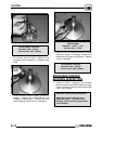
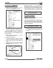
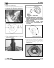
CAUTION: The driven clutch must be
disassembled from the helix end
to reducespring
pressure. Review all information below before
proceeding.
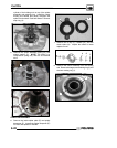
DRIVEN DISASSEMBLY/ASSEMBLY
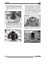
1. Remove driven clutch from the transmission input
shaft. Do not attempt disassembly of the driven
clutch from the outside snap ring. The driven
clutch must be disassembled from the helix side.
Do not disassemble from this side
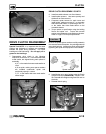
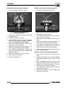
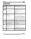
2. It is important to mark the position of the shaft,
cam cover, and sheave before disassembly or
use the “X”s on the components for reference.
This will aid in reassembly and helps to maintain
clutch balance after reassembly.
Mark Components Before Disassembly
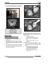
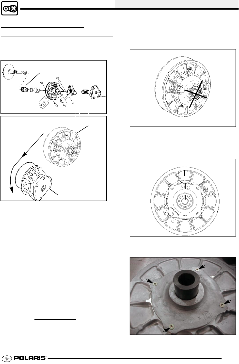
3. Remove the four torx screws that secure the cam
assembly (helix) using a T25 torx.
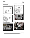
4. Place the driven assembly intothe Clutch Holding
Tool (PU--47086). Install the compression