


ELECTRICAL
10.19
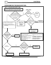
CHARGING SYSTEM “BREAK
EVEN”
TEST
CAUTION: Do not allow the battery cables to
become disconnected with the engine running.
Follow the steps below as outlined to reduce the
chance of damage to electrical components.
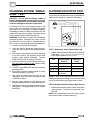
The “break even” point of the charging system is the
point at which the alternator overcomes all system
loads (lights, etc.) and begins to charge the battery.
Depending on battery condition and system load, the
break even point may vary slightly. The battery should
be fully charged before performing this test.
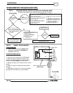
WARNING: Never start the engine with an ammeter
connected in series. Damage to the meter or meter
fuse will result. Do not run test for extended period of
time. Do not run test with high amperage accessories.
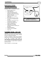
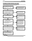
1. Connect a tachometer to the engine.
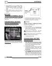
2. Using an inductive amperage metering device,
(set to DC amps) connect to the negative battery
cable
3. With engine off and the key, kill switch, and lights
in the ON position, the ammeter should read
negative amps (battery discharge). Reverse
meter lead if a positive reading is indicated.
4. Shift transmission into Park and start the engine.
With the engine running at idle,
observe meter
readings.
5. Increase engine RPM while observing ammeter
and tachometer.
6. Note RPM at which the battery starts to charge
(ammeter indication is positive).
7. With lights and other electrical loads off, the
“break even” point should occur at approximately
1500 RPM or lower.
8. With the engine running, turn the lights on and
engage parking brake lock to keep brake light on.
9. Repeat test, observing ammeter and tachometer.
With lights on, charging should occur at or below
2000 RPM.
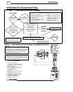
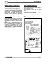
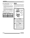
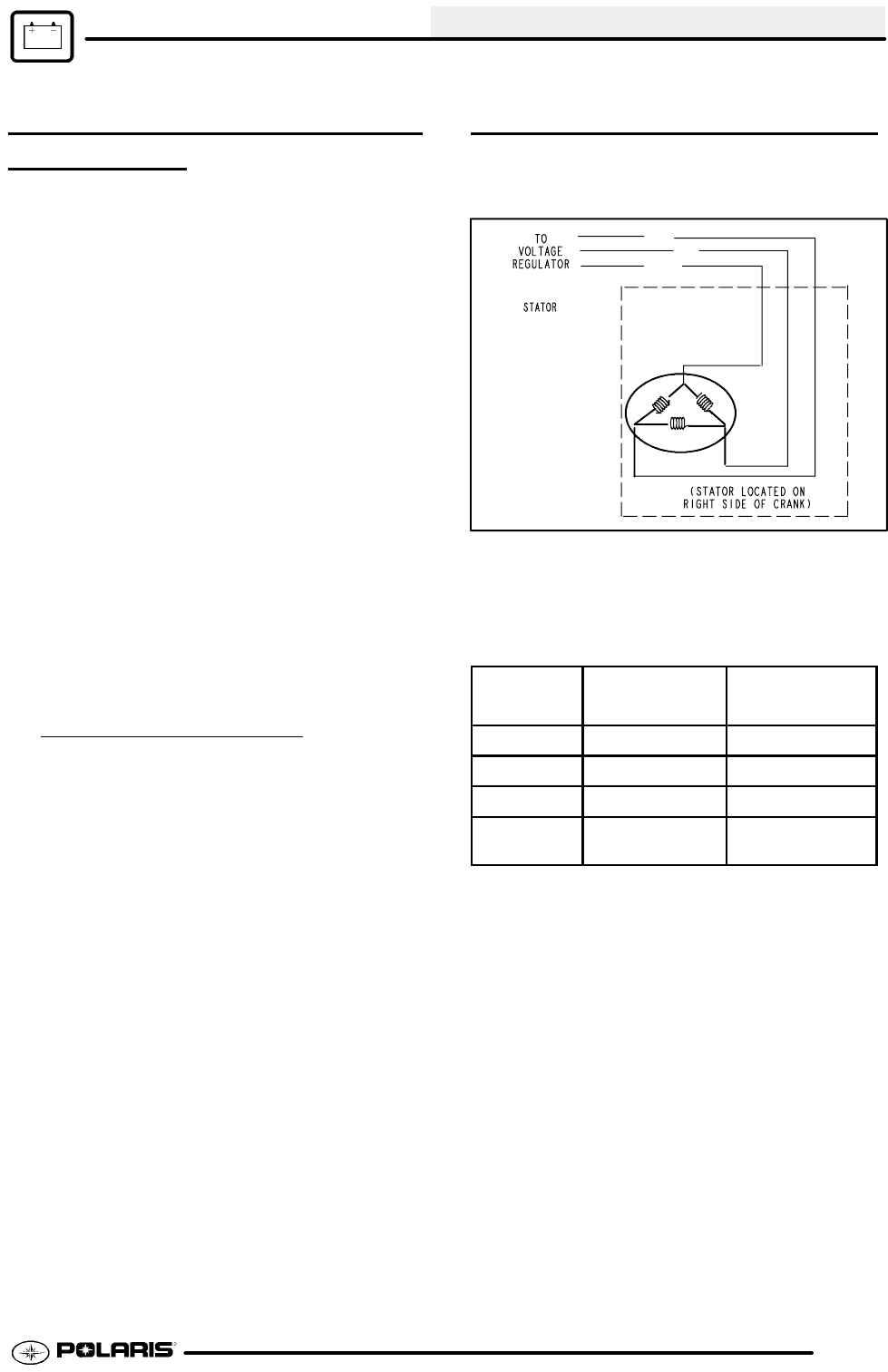
ALTERNATOR OUTPUT TEST
Threetestscanbeperformedusingamultimeterto
determine the condition of the stator (alternator).
Y1
Y2
Y3
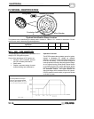
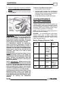
TEST 1: Resistance Value of Each Stator Leg
1. Measure the resistance value of each of the three
stator legs: Y1 to Y2, Y1 to Y3, and Y2 to Y3.
Each should measure 0.19 Ω±15 %.
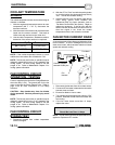
Test
Connect Meter
Wires To:
Reading In
Ohms
Charge Coil Y1 to Y2 0.19 Ω±15%
Charge Coil Y1 to Y3 0.19 Ω±15 %
Charge Coil Y2 to Y3 0.19 Ω±15 %
Charge Coil Y1, Y2, or Y3
to Ground
Open (Infinity)
NOTE: If there are any significant variations in ohm’s
readings between the three legs; it is an indication that
one of the three stator legs maybe weak or failed.
TEST2: Resistance Valueof StatorLeg to Ground
1. Measure the resistance value of eachof the stator
legs to ground: Y1 to Ground, Y2 to Ground, Y3 to
Ground.
NOTE: Any measurement other than Infinity (open)
will indicate a failed or shorted stator leg.