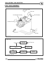
FUEL SYSTEM / FUEL INJECTION
4.10
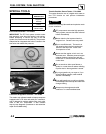
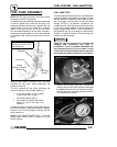
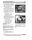
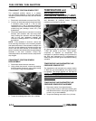
2. Turn on the key switch to activate the pump and
check the system pressure on the gauge. If
system pressure of 39 psi ± 3 is observed, the
ignition switch, ECU, fuel pump, and pressure
regulator are working properly. Turn the key
switch off and depress the valve button on the
tester to relieve the system pressure.
G If the pressure is too high or too low,
replace the fuel pump assembly.
3. If the pump did not activate (step 2), disconnect
the plug from the fuel pump. Connect a DC
voltmeter across terminals ’A’ and ’C’ in the plug,
turn on the key switch and observe if a minimum
of 7 volts is present. If voltage is between 7 and
14, turn key switch off and connect an ohmmeter
between the terminals ’A’ and ’C’ on the pump to
check for continuity.
G If there was no continuity between
the pump terminals, replace the fuel
pump/tank assembly.
G If the voltage was below 7 Vdc, test the
battery, ignition switch, wiring harness,
Load--shed/Relay, and ECU.
4. If voltage at the plug was good, and there was
continuity across the pump terminals, reconnect
the plug to the pump, making sure you have good,
clean connections. Turn on the key switch and
listen for the pump to activate.
G If the pump starts, repeat steps 1and
2 to verify correct pressure.
G If the pump still does not operate,
check for correct ECU operation by
plugging in a known--good ECU.
G If the pump still does not operate,
replace the pump/tank assembly.
FUEL PUMP/TANK ASSEMBLY
REPLACEMENT
NOTE: 800 EFI fuel connections are quick--connect
couplings vs 700 EFI connections.
WARNING: Always wear safety goggles when
working with high pressure or flammable fluids.
Failure to do so could result in serious injury or
complications.
NOTE: The fuel pump cannot be replaced as an
individual part, the entire fuel pump and fuel tank is
replaced as an assembly. Refer to your parts book for
the proper part number.
1. Disconnect the negative battery cable.
2. Remove the side panels and front cab assembly.
Refer to “COVER PANEL REMOVAL” in Chapter
5 for details.
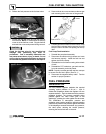
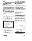
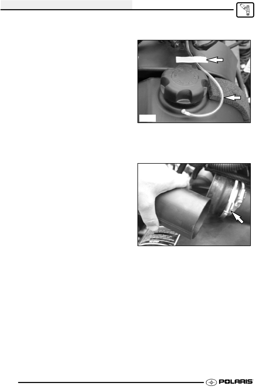
3. Remove the gas tank cover vent hose. Be sure to
properly route the vent hose upon reassembly.
Pic 1
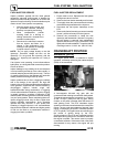
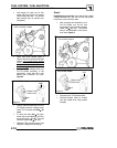
4. Remove the clamps on the PVT intake duct and
remove the PVT duct.
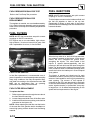
5. With all the body panels removed from the front of
the ATV and the gas tank exposed, disconnect
the pump wiring harness.
WARNING: Wear safety goggles while performing
this procedure, failure to do so could result in serious
injuries.


