


FUEL SYSTEM / FUEL INJECTION
4.7
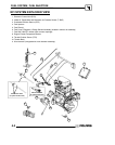
ELECTRONIC FUEL
INJECTION
SYSTEM
OVER
VIEW
General
The Electronic Fuel Injection (EFI) system is a
complete engine fuel and ignition management
design. This system includes the following principal
components:
G Fuel Pump
G Fuel Rail
G Fuel Line(s)
G Fuel Filter(s)
G Fuel Injectors
G Pressure Regulator
G Throttle Body / lntake Manifold
G Engine Control Unit (ECU)
G Ignition Coils
G Coolant Temperature Sensor
G Throttle Position Sensor (TPS)
G Crankshaft Position Sensor (CPS)
G Intake Air Temperature and
Barometric Air Pressure Sensor
(T--BAP)
G Wire Harness Assembly
G Check Engine Light (MIL)
EFI OPERATION OVERVIEW
The EFI system is designed to provide peak engine
performance with optimum fuel efficiency and lowest
possible emissions. The ignition and injection
functions are electronically controlled, monitored and
continually corrected during operation to maintain
peak performance.
The central component of the system is the Boscht
Engine Control Unit (ECU) which manages system
operation, determining the best combination of fuel
mixture and ignition timing for the current operating
conditions.
An in--tank electric fuel pump is used to move fuel
from the tank through the fuel line andin--linefuelfilter.
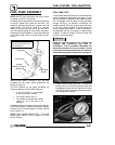
The in--tank fuel pressure regulator maintains a
system operating pressure of 39 psi and returns any
excess fuel to the tank. At the engine, fuel is fed
through the fuel rail and into the injectors, which inject
into the intake ports. The ECU controls the amount of
fuel by varying the length of time that the injectors are
”on.” This can range from 1.5--8.0 milliseconds
depending on fuel requirements. The controlled
injection of the fuel occurs each crankshaft revolution,
or twice for each 4--stroke cycle. One--half the total
amount of fuel needed for one firing of a cylinder is
injected during each injection. When the intake valve
opens, the fuel/air mixture is drawn into the
combustion chamber, ignited. and burned.
The ECU controls the amount of fuel being injected
and the ignition timing by monitoring the primary
sensor signals for air temperature, barometric air
pressure, engine temperature, speed (RPM), and
throttle position (load). These primary signals are
compared to the programming in the ECU computer
chip, and the ECU adjusts the fuel delivery and
ignition timing to match the values.
During operation the ECU has the ability to re--adjust
temporarily, providing compensation for changes in
overall engine condition and operating environment,
so it will be able to maintain the ideal air/fuel ratio.
During certain operating periods such as cold starts,
warm up, acceleration, etc., a richer air/fuel ratio is
automatically calculated by the ECU.
INITIAL STARTING/PRIMING PROCEDURE
NOTE: The Injection system must be purged of all air
prior to the initial start up, and/or any time the system
has been disassembled.
If the EFI system is completely empty of fuel or has
been disassembled and repaired:
1. Cycle the key switch from “OFF” to “ON” 6 times,
waiting for approximately 3 seconds at each “ON”
cycle to allow the fuel pump to cycle and shut
down.
2. Once step 1 is completed, turn the key switch to
“START” until the engine starts or 5 seconds
seconds has passed.
3. If the engine failed to start, repeat step 1 for 2
more cycles and attempt to start the engine.
If the enginefails to start, a problem maystill exist, and
should be diagnosed.
NOTE: Accurate testing of EFI components is
recommended utilizing the Polaris Diagnostic
Software (dealer only).