


FUEL SYSTEM / FUEL INJECTION
4.16
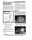
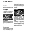
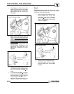
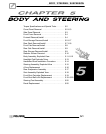
G With engine off, back out air flow
screw until it no longer is in contact
with throttle plate cam. The throttle
plate should seal off throttle bore
completely.
Figure 1
Back air flow screw out
until no contact is made
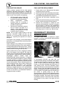
G Open and close throttle plate a
couple of times to ensure full throttle
closing. Do not snap closed, as
this
could cause unnecessary
throttle
plate to throttle body
interference
and/or
damage.
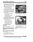
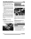
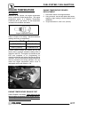
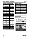
G Set up the TPS voltage check tool
PN PU--47082 according to the
instructions. Verify that the 9 volt
battery has a minimum of 6 volts.
Figure 2.
Figure 2
Red
Pink
Black
Should read
.528v
Vdc
Black Probe
Red Probe
.528
Tool PN PU--47082
R
Y
BK
G Using a voltmeter attached to tool PN
PU--47082 check the voltage output
of the TPS. It should read .528 ± .01
volts.
G If it does not read .528 ± .01 volts,
loosen the screw holding the TPS to
the throttle body. Rotate TPS until
voltmeter reads .528 ± .01 volts.
G Retighten TPS mounting screw, and
verify the voltage did not change.
Step 2
Establishing correct flow: Now that the zero offset
voltage has been set, you can now set the throttle
body to the correct air flow value.
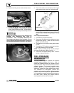
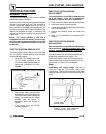
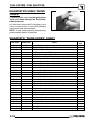
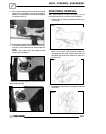
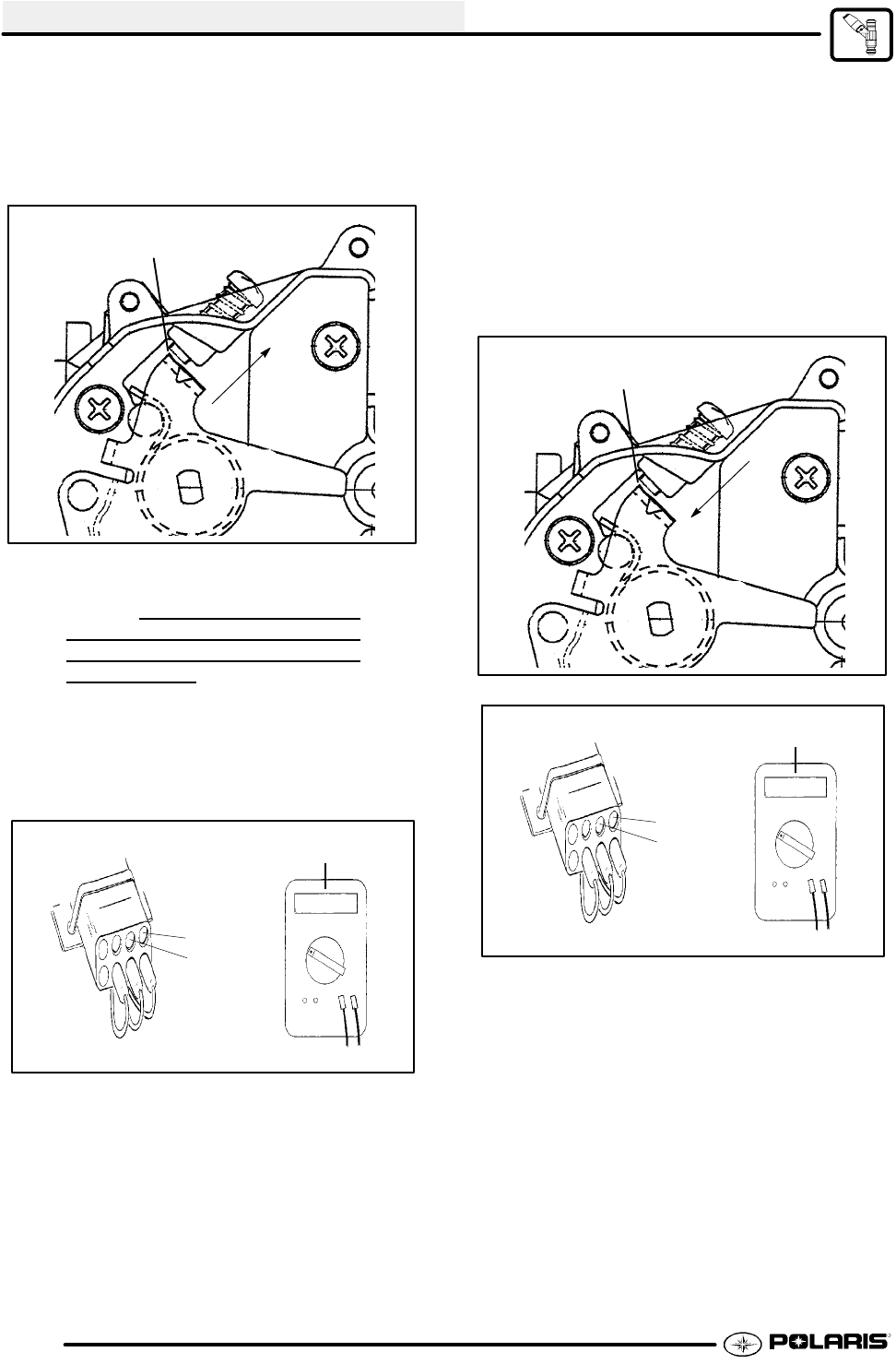
G With voltmeter still attached to tool
PN PU--47082, turn the air flow
adjustment screw until the voltmeter
reads .710 ± .01 volts. The throttle
body is now adjusted to the correct
flow value Figure 3.
Figure 1
Turn air flow screw in
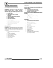
Figure 3
Red
Pink
Black
Should read
Vdc
Black Probe
Red Probe
.710
Tool PN PU--47082
R
Y
BK
.710v
G Reconnect the TPS harness lead
G Reinstall throttle cable on throttle
cam and install cover. Adjust cable
freeplay.