


ELECTRICAL
10.3
INSTRUMENT CLUSTER
OVER
VIEW
Ill.1
Ill.2
9
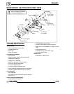
Introduction
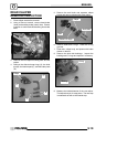
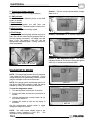
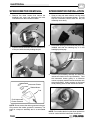
Refer to Illustration 1:
The Polaris ATV Instrument Cluster is powered by
battery voltage (12 VDC) and requires inputs from the
engine RPM, transmission gear, and wheel speed
sensor for proper operation. Two harnesses plug into
the cluster head; one from the right front wheel speed
sensor, and one from the vehicle main harness. A
non-serviceable internal memory battery maintains
odometer and hour meter data when the machine is
not running. The illumination lamp inside the gauge
is non-serviceable and is designed to last for the life
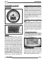
of the unit. (A) The speedometer needle indicates
speed from an electronic wheel speed sensor located
on the right front brake caliper bracket and the needle
also flashes during a warning condition. The
speedometer needle indicates speed in MPH and
KPH. NOTE: A flashing needle could indicate a
hot engine, low battery warning, or the No. 10 Pin
could be grounded. (B) The speedometer features
numbers in Mile Per Hour (MPH) and Kilometers Per
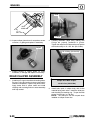
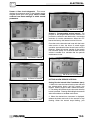
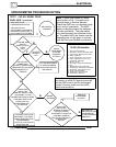
Hour (KPH). (C) The Rider Information Center
performs a number of functions (See Illustration 2):
1. Odometer/Tachometer/Trip meter/Hour
Meter
* Odometer records the miles traveled by the ATV.
*Tachometer displays engine RPM. This feature will
also display with the vehicle in motion NOTE: Small
RPM fluctuations from day to day are normalbecause
of changes in humidity, temperature, and elevation.
*Trip meter records the miles traveled by the ATV if
reset before each trip or total miles to 999. To reset
the trip meter, select the trip meter mode. Press and
hold the mode button (override button) until the total
changes to 0. NOTE: IntheRiderInformationCenter,
the trip meter display contains a decimal point, but the
odometer displays without a decimal point.
*Hour Meter logs the total hours the engine has been
in operation.
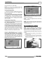
2.Programmable Service
Interval/Diagnostic
Mode
*Service Interval -- The purpose of the
programmable service interval is to provide the
consumer and the dealer with a convenient way to
schedule routine maintenance. Whenthe ATV leaves
the factory, this feature is set at “50 hours”. When the
first 50 hours of engine operation are finished the
wrench icon will flash for 10 seconds each time the
ATV is started as a reminder that ATV maintenance
is due. NOTE: To reset the Service Interval, follow the
directions on the on Page 10.5, “Setting New Service
Interval”.
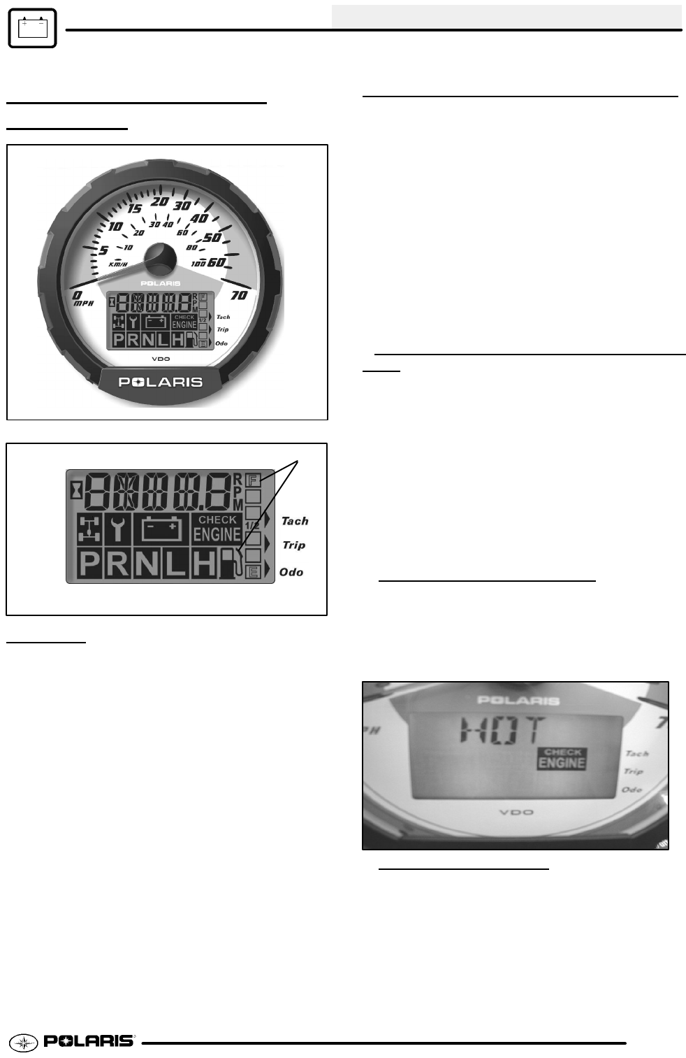
3. Check Engine Warning
Indicator
The word HOT will display alpha numerically whenthe
engine is overheating. Do not continue to operate the
ATV if this warning appears. Refer to Chapter 3
“Cooling System Troubleshooting” for help with
diagnosis of overheating.
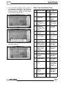
4. High/Low Battery Voltage
This warning usually indicates that the ATV is being
operated at an RPM too low to keep the battery
charged. A low battery warning may also occur under
normal operation if the machine is at idle and high
electrical load (lights, cooling fan, accessories) is
applied. Driving at a higher RPM or connecting a
battery charger will usually clear the warning.