MAINTENANCE
2.14
THROTTLE CABLE /
ELECTRONIC
THROTTLE
CONTROL (ETC
SWITCH)
ADJUSTMENT
1. Slide boot off throttle cable adjuster and jam nut.
2. Place shift selector in neutral and set parking
brake.
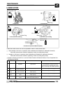
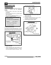
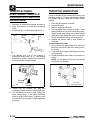
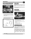
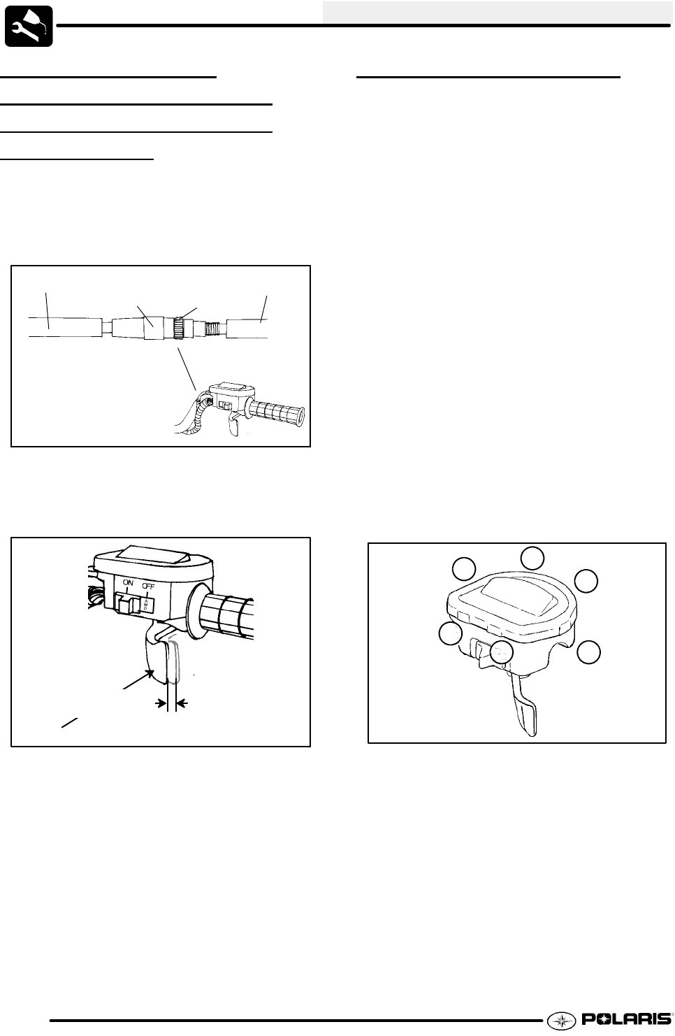
3. Loosen lock nut on in-line cable adjuster (Ill. 1).
Boot
Adjuster
Sleeve
Lock-
nut
Boot
Ill. 1
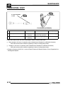
4. Turn adjuster until 1/16″ to 1/8″ freeplay is
achieved at thumb lever. (Ill. 2). After making
adjustments, quickly actuate the thumb lever
several times and reverify freeplay.
1/16″ -1/8″
Freeplay
Direction
of travel
Ill. 2
5. Tighten lock nut securely and slide boot
completely in place to ensure a water-tight seal.
6. Turn handlebars from left to right through the
entire turning range. If idle speed increases,
check for proper cable routing. If cable is routed
properly andin good condition, repeat adjustment
procedure.
THROTTLE INSPECTION
Check for smooth throttle opening and closing in all
handlebar positions. Throttle lever operation should
be smooth and lever must return freely without
binding.
1. Place the gear selector in neutral.
2. Set parking brake.
3. Start the engine and let it idle.
4. Turn handlebars from full right to full left. If idle
speed increases at any point in the turning range,
inspect throttle cable routing and condition. Adjust
cable tension as needed until lock--to--lock turning
can be accomplished with no rise in engine rpm.
5. Replace the throttle cable if worn, kinked, or
damaged.
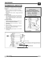
To remove the ETC cover:
1. Use a medium flat blade screwdriver and insert
blade into the pocket of the cover starting on the
#1 position.
2. Twist screwdriver slightly while lifting on the cover
to release snap.
3. Repeat procedure at the other five locations as
shown.
NOTE: Do not attempt to remove cover until all
latch points are released.
1
2
3
4
5
6
5
6
ETC Cover
Removal Sequence
Ill. 1


