


Page 5-48 400 SERIES MAINTENANCE MANUAL
Rev. C P/N 190-00140-05
5.7.6.16 MAIN Lateral Flag Output
Measure J1-23 relative to J1-24. Load—333 ohms (Three 1000 ohm loads) across J1-23 and
J1-24.
‘HIDE’______ (+375
r
80 mV)
IN VIEW ______ (0 r25 mV )
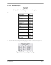
5.7.6.17 MAIN Vertical Flag Output
Measure J1-29 relative to J1-30. Load—333 ohms (Three 1000 ohm loads) across J1-29 and
J1-30.
‘HIDE’______ (+375
r
80 mV)
IN VIEW ______ (0
r
25 mV )
5.7.6.18 MAIN Lateral Super Flag Output
1. Measure at J1-17. Load resistor to ground such that it will sink 500 mA when attached to
AIRCRAFT POWER. (J1-19 or 20). Note applicable output will source this current when
active. Note if the load is sized for 13.8 V (28 ohms/7W) operation then this test should not
be run at 27.5 V (56 ohms/14 W).
‘HIDE’______ (AIRCRAFT POWER minus 1.5 VDC min)
IN VIEW ______ (0.25 VDC max )
5.7.6.19 MAIN Vertical Super Flag Output
1. Measure at J1-18. Load—Resistor to ground such that it will sink 500 mA when attached to
AIRCRAFT POWER. (J1-19 or 20). Note: applicable output will source this current when
active. Note if the load is sized for 13.8 V (28 ohms/7W) operation then this test should not
be run at 27.5 V (56 ohms/14W).
‘HIDE’______ (AIRCRAFT POWER minus 1.5 VDC min)
IN VIEW ______ (0.25 VDC max)