


Page 4-4 400 SERIES MAINTENANCE MANUAL
Rev. C P/N 190-00140-05
4.5.2.1 Disassemble the CDU Assembly
x Remove the Flex Assemblies (Figure 7-4)
1. Remove the VOL w/’C’ and VOL w/’V’ Knobs (18 and 19).
2. Remove the Push ‘CRSR’ and Push ‘C/V’ knobs (21, 22, 20, and 28).
3. Remove the Hex Nuts holding the Push ‘CRSR’ and Push ‘C/V’ shafts to the
CDU Bezel (13).
4. Disconnect the Flex Assembly (25) from the LCD (9).
5. Back the Flex Assembly (25) out of the Bezel.
6. Remove the two screws (2) attaching the Interface Board (5) to the CDU Bezel
(13).
7. Back the Flex Assembly (26) out of the Bezel.
x Remove the Interface Board (Figure 7-4)
Remove the two Hex Nuts (6 and 31) holding the Rotary Pots (3 and 4) to the
Interface Board (5) and slide the Interface Board off the Pot Shafts.
x Remove the LCD Assembly (Figure 7-4)
Remove the four screws (2) holding the LCD Assembly (9) to the Bezel (13).
x Remove the Inlay Lens and Keyboard PCB (Figure 7-4)
Remove the five screws (12) and pop the Inlay Lens out and remove the Keyboard
PCB (15) from the CDU Bezel (13).
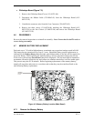
4.5.3 Separate the Main and Nav Chassis (Figure 7-1)
1. Remove two screws (211-60237-10).
2. Loosen the rear hinge Special Shoulder Screws (211-00052-00) from the Main
Chassis (011-00283-X0) and fold the Nav Chassis (011-00282-00) over. To totally
separate the chassis, remove the threaded Hinge Pins (211-00054-00) from the Nav
Chassis using a .050 (1.3 mm) Hex Driver Tool.
3. Disconnect the ribbon cable (325-00063-00).
4. Disconnect the fan power leads from the Main Chassis.