


400 SERIES MAINTENANCE MANUAL Page 3-5
P/N 190-00140-05 Rev. C
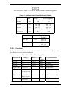
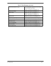
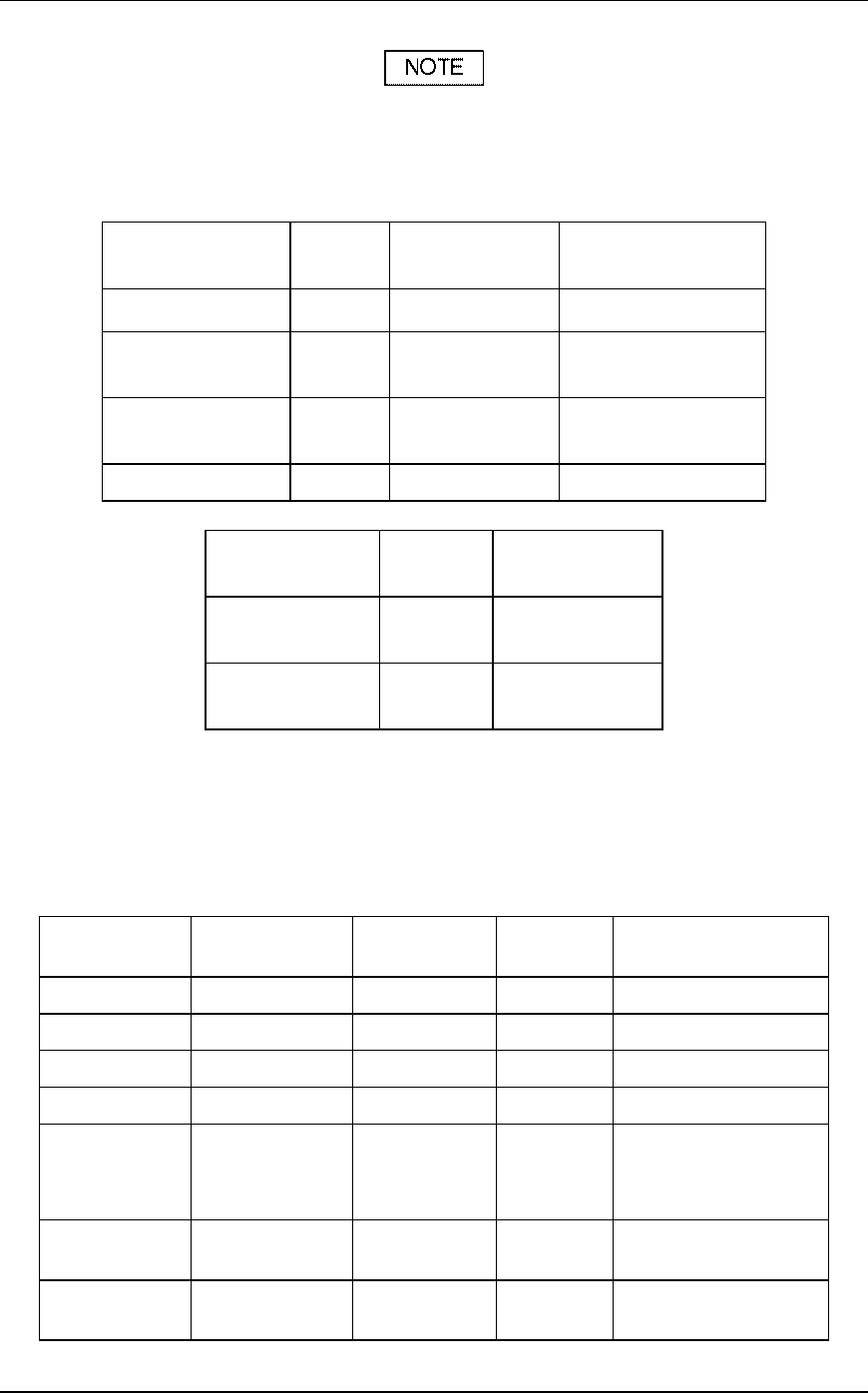
The values listed in Table 3-1 are with the display backlight at maximum brightness.
Table 3-1. Unit Board Power Supply Max Current Allowed
Unit (Main Board) Unit
Status
Max Current (A)
@ 27.5 V
Max Current (A)
@ 13.8 V (Optional)
GPS 400 ON 0.66 1.32
GNC 420 ON RX—0.99
TX—3.36
RX—1.98
TX—7.32
GNS 430 ON RX—1.17
TX—3.98
RX—2.34
TX—7.96
ALL UNITS OFF 0.014 0.011
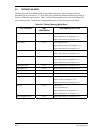
16 Watt Units Unit Status Max Current (A)
@ 27.5 V
GNC 420A ON RX—0.99
TX—3.36
GNS 430A ON RX—1.17
TX—3.98
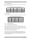
3.3.2.2 Com Board
Replace the Main Board if any voltage on the Com Board is not within tolerance. Replace the
Com Board if excessive current is measured.
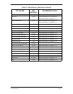
Table 3-2. Com Board Power Supply Tolerances
Connector/Pin Voltage (V) Tolerance (V) Max
Current
Conditions/Remarks
J26 Pin 5 +5 4.9 to 5.3 90 mA
J26 Pin 1 +12 11.5 to 13 420 mA TX Mode
J26 Pin 2 -12 -16 to -11 35 mA Receive Mode
J2 Pin 11 & 12 +11 to +33 15 mA Receive Mode
J2 Pin 11 & 12 +13.75
(14/28V 10 Watt
Units Only)
r.2
6.0 A DC
1
TX Mode
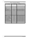
J2 Pin 11 & 12
+27.5 (28V 10
Watt Units Only)
r.4
3.0 A DC
1
TX Mode
J2 Pin 11 & 12
+27.5 (16 Watt
Units Only)
r.4
3.0 A DC
1
TX Mode
1
Modulated transmitter operating into a 50 ohm load.