


400 SERIES MAINTENANCE MANUAL Page B-15
P/N 190-00140-05 Rev. C
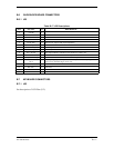
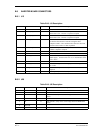
B.6 GLIDESLOPE BOARD CONNECTORS
B.6.1 J25
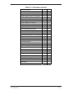
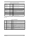
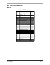
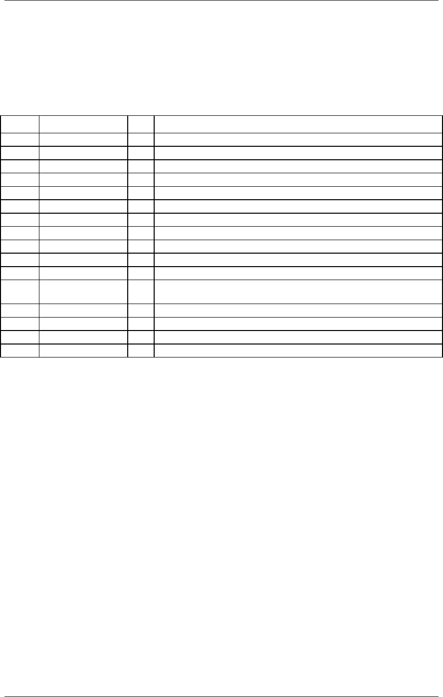
Table B-17. J25 Descriptions
Pin # Pin Name I/O DESCRIPTION
1 +12VDC I
2 +5VDC I
3 GND I Ground.
4 -12VDC I
5 G/S IF AGC O The IF AGC output. 10K output impedance.
6 G/S Composite O Not Used.
7 G/S SERIAL_IN I Serial input from Main Board.
8 G/S SERIAL_OUT O Serial output from G/S Board to Main Board.
9 G/S + FLAG O This output indicates whether course deviation is valid or not.
10 G/S + UP O This is the vertical course deviation output for the G/S.
11 G/S -[COMMON] O Reference for G/S + UP and G/S + FLAG outputs.
12 GS SUPERFLAG
OUT
O G/S superflag output is an open collector output. The G/S superflag will be
active (low) when the flag is out of view.
13 KEY Polarization Pin
14 RF AGC O Not Used
15 SPARE SPARE
16 KEY Polarization Pin
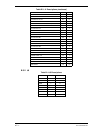
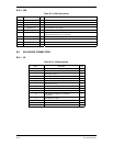
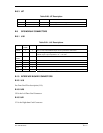
B.7 KEYBOARD CONNECTORS
B.7.1 J23
See description of LCD Flex (J12).