


Page B-6 400 SERIES MAINTENANCE MANUAL
Rev. C P/N 190-00140-05
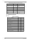
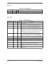
B.3.5 J12
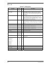
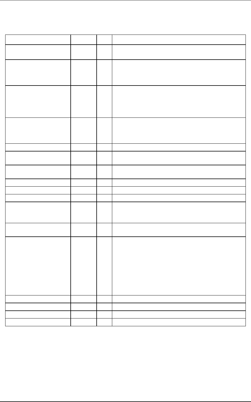
Table B-7. J12 Descriptions
Pin Name Pin # I/O Description
LD1 through LD8 46-50
3-5
O LOWER half display DATA output.
CLK_ROW 6 O Pulse high for typically 310 ns at a period of 33.236 us
(30.088 kHz). This line loads the next row of data in the
display drivers. There are 66 CLK_ROW pulses for each
FLM pulse.
CLK_SHIFT 7 O Pulse high for a typical 120 or 180 ns. Pulses come in bursts
of 90 with about 180 ns of low time between each. The
bursts of 90 come at the CLK_ROW frequency. The rising
edge of the first pulse in a burst of 90 is about 1.22 us after
the rising edge of a CLK_ROW pulse.
FLM 8 O First Line Marker that pulses high for 33.236 us (30.088
kHz) at period of 2.19359 ms (455.873 Hz). The rising edge
of FLM is about 1.1 us after the rising edge of a CLK_ROW
pulse.
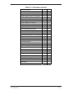
LCD_OFFN 9 O LCD OFF Not is a output that turns off the display if low.
T1 10 I Thermistor 1 input is used to measure LCD temperature.
Resistance of input is 10 k ohm to VCC.
T2 11 I Thermistor 1 input is used to measure heater temperature.
Resistance of input is 2.2 k ohm to VCC.
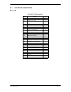
VCC 12 O
LCD_HV 13 O LCD contrast voltage.
GND 14 O Ground.
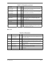
SPARE 15,
30..37,65
66..70
BEZEL_TEMP 16 I Bezel temperature is used by the board to measure
temperature.
PB_OUT_A
PB_OUT_B
PB_OUT_C
PB_OUT_D
PB_IN_A
PB_IN_B
PB_IN_C
PB_IN_D
55
20
54
19
53
18
52
17
O
O
O
O
I
I
I
I
Push Button Matrix.
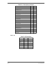
GND 21 O Ground.
NOT USED 22
NOT USED 23
NOT USED 24