


Page 3-6 400 SERIES MAINTENANCE MANUAL
Rev. C P/N 190-00140-05
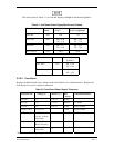
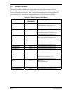
3.3.2.3 Glideslope Board
Replace the Main Board if any voltage on the G/S Board is not within tolerance. Replace the G/S
Board if excessive current is measured.
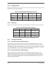
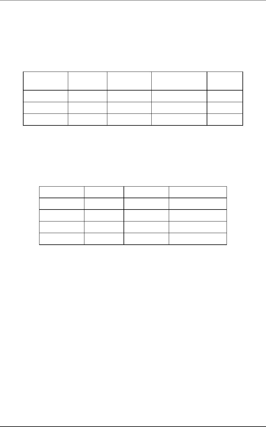
Table 3-3. Glideslope Board Power Supply Tolerances
Connector/Pin Voltage (V) Tolerance (V) Max Current
(mA)
Comments
J25 Pin 2 + 5.1
r 0.2
100 91 mA typ
J25 Pin 1 + 12.5
r 1.0
100 92 mA typ
J25 Pin 4 -12.5
r 2.0
12.5 10 mA typ
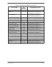
3.3.2.4 NAV Board
Replace the Nav Board if any voltage is not within tolerance or if excessive current is measured.
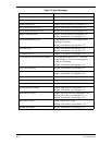
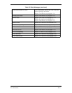
Table 3-4. Nav Board Power Supply Tolerances
Connector/Pin Voltage (V) Tolerance (V) Max Current (mA)
J10 Pin 1 + 12.5
r0.2
300
J10 Pin 2 + 5.1
r0.1
200
J10 Pin 4 -12.5
r0.2
35
J6 Pin 44 + 28
r5.0
1100
3.3.3 Processor Clock Check
3.3.3.1 Internal Clock Check—Main Processor
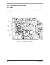
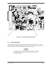
Measure the clock speed of the Main Processor (located on the Main Board, Figure 3-5) by
placing an oscilloscope probe at I100, pin 125 (remove the Map Board to gain access to I100).
The frequency should be approximately 32.7 MHz. If the clock is not operational, check J8-4 for
32.7 MHz (approximate). If the 32.7 MHz signal is present, replace the Main Board. If the Main
Board replacement does not repair the fault, replace the GPS Module.
3.3.3.2 Internal Clock Check—GPS Processor
Measure the clock speed of the GPS Processor (located on the Main Board, Figure 3-5) by
placing an oscilloscope probe at I1110, pin 125. The frequency should be approximately 32.7
MHz. If the clock is not operational, check J8-4 for 32.7 MHz (approximate). If the 32.7 MHz
signal is present, replace the Main Board. If the Main Board replacement does not repair the
fault, replace the GPS Module.