


Page 5-44 400 SERIES MAINTENANCE MANUAL
Rev. C P/N 190-00140-05
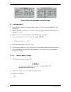
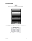
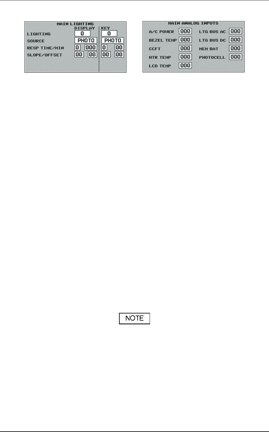
Figure 5-7. Main Lighting and Main Analog Test Pages
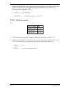
B. Lighting Bus DC
1. Using the Main Lighting Test Page, change source to 14 VDC in both the DISPLAY and
KEY fields.
2. Attach 12.0 VDC to unit pin J1-39. Ensure the power supply ground is connected to unit
ground (J1-77, 78).
3. Monitor the Test(s) results using the Main Analog Inputs Test Page
4. To convert the displayed value to volts: V = value x 0.09299.
Measured Value______ VDC
5. Verify measured value is 12.0 r5% VDC.
6. Vary the input amplitude (+14 V max), and verify the display lighting changes accordingly.
7. Cover the photocell and verify the input amplitude (+14 V max), verify the key lighting
changes accordingly.
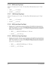
5.7.6.6 Memory Battery Voltage
1. Verify memory battery voltage is OK.
To convert the displayed value to volts: V = value x 0.02. The
unit typically alarms at 2.46 V.
2. The battery voltage for a new battery should be > 2.9 V.
3. Verify V > 2.68 volts.
_____OK