


400 SERIES MAINTENANCE MANUAL Page 3-1
P/N 190-00140-05 Rev. C
SECTION 3
TROUBLESHOOTING
Each unit in the 400 Series contains static sensitive components.
Observe proper anti-static procedures when testing the unit.
Hazardous voltages exist on the Inverter Board (all units).
Under normal operating conditions the voltages range up to
2500 Vac peak to peak. Under open circuit conditions voltages
can range over 8000 Vac peak to peak. Exercise extreme
caution during unit troubleshooting. Death or serious injury
could result from electrical shock. See other general
maintenance warnings and cautions on page ii.
3.1 TROUBLESHOOTING EQUIPMENT
The equipment used in testing a unit can be used to troubleshoot a faulty unit. See Sections 2 and
5.
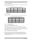
3.2 TROUBLESHOOTING ORDER
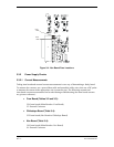
Start troubleshooting a unit by following steps one through three listed below (not necessarily in
the order listed). Once it has been determined that these three items are not the cause of failure,
proceed with troubleshooting using the static messages and performance testing (paragraphs 3.4
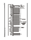
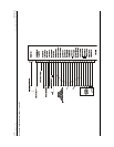
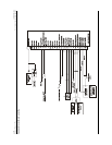
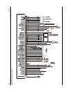
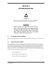
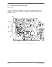
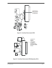
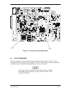
and 3.5). To help in the troubleshooting process, a block diagram and external connectors are
shown at the end of this section. In addition, Appendix B describes all of the input/output signals
for all of the unit’s internal and external connectors.
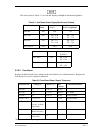
1. Fuses (Paragraph 3.3.1).
2. Power Supply Checks (Paragraph 3.3.2).
3. Processor Clock Check (Paragraph 3.3.3).