


400 SERIES MAINTENANCE MANUAL Page 4-7
P/N 190-00140-05 Rev. C
x Glideslope Board (Figure 7-3)
1. Remove the Glideslope Board Cover (115-00221-00).
2. Disconnect the Ribbon Cable (325-00063-01) from the Glideslope Board (012-
00212-XX).
3. Unsolder the connector wire from the Coax Connector (330-00070-03).
4. Remove the three screws (211-60234-04) attaching the Glideslope Board (012-
00212-XX) to the Nav Chassis (125-00035-00) and remove the Glideslope Board
(012-00212-XX).
4.6 REASSEMBLY
Reverse the removal instructions to reinstall an assembly. Note: Ensure that Loctite
is used on
screws during reassembly.
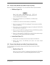
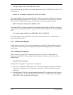
4.7 MEMORY BATTERY REPLACEMENT
Each unit uses a 3 V built-in lithium battery to maintain user waypoints/settings stored in RAM.
This battery has an operational life of up to 5 years. Should the battery require replacement, as
indicated by the Memory Battery Low message, partial disassembly of the unit will be required to
access the battery. When replacing the memory battery, all user waypoints/settings may be lost.
If this occurs, the message Stored Data Lost will be displayed. The unit must then be attached to
an antenna, allowed to search the sky and collect new almanac data before it will be usable again.
This process may take 20-30 minutes. Before beginning replacement of the memory battery,
transfer all waypoints and routes to a user data card so that they may be transferred back to the
unit following battery replacement.
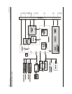
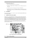
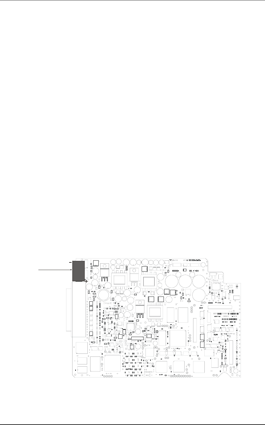
MEMORY
BATTERY
B-170
Figure 4-2. Memory Battery Location (Main Board)
4.7.1 Remove the Memory Battery