


400 SERIES MAINTENANCE MANUAL Page 4-5
P/N 190-00140-05 Rev. C
4.5.4 Remove Faulty Boards from the Main Chassis Top Cavity
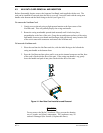
Remove the Top Cover (see paragraph 4.5.1) to access the Main Chassis Top Sub-assemblies.
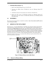
x COM Board (Figure 7-2)
Steps 5 and 6 apply to 28V/10W units only. 14/28V and
28V/16W units have no posistor, no brass spacers, and use two
screws to hold down the PA transistor.
1. Remove the Com Board Covers (115-00203-00, 115-00205-00 and
115-00207-00).
2. Unsolder the wire from Coax Cable Connector (330-00070-04).
3. Remove two screws (211-63234-10) attaching the 25-pin connector to the Main
Chassis (125-00034-01).
4. Remove three screws (211-60234-06) securing the Com Board (012-00214-XX)
to the Main Chassis (125-00034-01).
5. Remove screw (211-60234-06) attaching the Posistor (925-D2120-00) to the Hex
Standoff (214-00023-00) on one side of the transistor.
6. Remove two Hex Standoffs (214-00023-00) on each side of the transistor using a
0.187-inch (3/16”) hex socket tool and remove Com Board.
x Inverter Board (Figure 7-2)
1. Disconnect the wire connector from the Inverter Board (012-00256-00).
2. Remove three Screws (211-60234-06) and remove the Inverter Board
(012-00256-00).
4.5.5 Remove Faulty Boards from the Main Chassis Underside Cavity
To access the bottom sub-assemblies, hinge open the Main Chassis from the Nav Chassis
(paragraph 4.5.3).
x Map Board (Figure 7-2)
Remove the screw (211-60234-11) attaching the Map Board (012-00296-00) to
the Main Board (012-00347-3X) and lift the Map Board off the Connector.