


400 SERIES MAINTENANCE MANUAL Page 5-3
P/N 190-00140-05 Rev. C
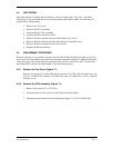
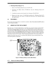
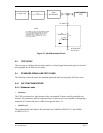
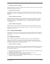
UNIT UNDER
TEST
BIRD
WATTMETER
30 dB
50 WATT ATTENUATOR
50 OHM LOAD
RF INPUT
ATTENUATED
RF OUTPUT
NOTE
50 OHM LOAD IS NOT REQUIRED
IF 30 dB ATTENUATOR IS USED.
THE 30 dB ATTENUATOR WILL
LOWER THE VSWR TO < 1.1:1
EVEN IF LEFT OPEN ON THE
OUTPUT SIDE.
RF
ATTENUATOR
8.2k
51 OHMS
Figure 5-1. 40 dB Attenuator Circuit
5.3 TEST SETUP
The test setup is configured by the repair station. Load and signal information given in Section 2
and Appendix B can aid in the test setup.
5.4 STANDARD SIGNAL AND TEST LOADS
The following section describes the standard signal and loads for testing the 400 Series units.
5.4.1 VHF COM TRANSCEIVER
5.4.1.1 Standard Loads
Antennas
The VHF com transceiver shall operate with a conventional 50 ohm vertically polarized com
antenna. The transmitter shall be terminated into a 50 ohm resistive load capable of dissipating a
minimum of 50 watts and with a VSWR of not greater than 1.2:1.
Audio Load
The standard audio load shall be 500 ohms between COMM AUDIO HI J2-7 and COMM
AUDIO LO J2-19.