


Page 5-6 400 SERIES MAINTENANCE MANUAL
Rev. C P/N 190-00140-05
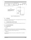
G/S Super Flag Load (G/S SUPER FLAG OUT)
One standard super flag load shall be 56 ohms connected between G/S SUPER FLAG OUT J6-38
and GND J6-41.
ARINC 429 Transmitter Load (VLOC 429 OUTA/OUTB)
The standard ARINC 429 transmitter load shall be 2.4K ohms resistance and 250 pF capacitance
between the differential outputs VLOC 429 OUTA J6-24 and VLOC 429 OUTB J6-23, and 2.4K
ohms resistance and 250 pF capacitance connected from each of the outputs to ground.
RS232 Transmitter Load (VLOC SERIAL OUT)
The standard RS232 transmitter load shall be 3000 ohms measured from the RS232 serial output
to ground. One standard load shall be connected between VLOC SERIAL OUT J10-10 and GND
J10-3.
NAV Audio Output Load (NAV AUDIO HI to NAV AUDIO LO)
The standard audio output load shall be 500 ohms, connected between NAV AUDIO HI J6-16
and NAV AUDIO LO J6-17.
5.4.4 VOR Standard Signals
All RF input levels for the NAV receiver requirements are specified in dBm and do not require a
6 dB attenuator on the output of the signal generator provided the signal generator is calibrated
into 50 ohms.
5.4.4.1 Standard Test Signals
Unless otherwise specified, the RF input signals shall be at a level of -53 dBm and have a
frequency within 0.001% of the assigned carrier frequency in addition to the characteristics
outlined below.
Standard VOR Test Signal
Standard VOR test signal is composed of two components:
a) a RF carrier, amplitude modulated 30% with a 9960 Hz signal that is frequency modulated at
30 Hz with a deviation ratio of 16 (frequency deviation of +/-480 Hz) for Reference phase
(REF), and
b) a variable phase (VAR) 30 Hz signal amplitude modulated 30% with respect to the reference
phase signal (REF). The RF input signal shall be at a level of -53 dBm and have a frequency
within 0.001% of the assigned carrier frequency.