


Page 5-50 400 SERIES MAINTENANCE MANUAL
Rev. C P/N 190-00140-05
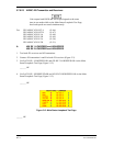
2. Measure at applicable pin. Load—Resistor to external voltage source such that it will source
275 mA when grounded. Note: applicable output will sink this current when active
(18 ohms/2W when pulled up to 5V).
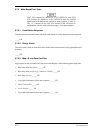
ACTIVE______ (0.3 VDC max)
INACTIVE ______ (NLT pull-up voltage at minus 0.2V )
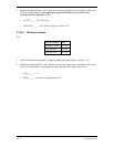
5.7.6.21 OBI Serial Interface
For:
SIGNAL NAME PIN
GPS OBI CLOCK (J1-43)
GPS OBI DATA (J1-44)
GPS OBI SYNC (J1-45)
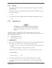
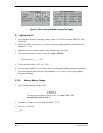
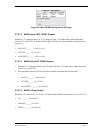
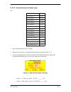
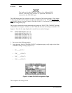
1. Use the Main Discrete Outputs Test Page to monitor the following test (Figure 5-10).
2. Measure at applicable pin. Load: Resistor to external voltage source such that it will source
25 mA when grounded. Note applicable output will sink this current when active.
LOW______ < 1 V
HIGH______ Load source voltage minus 0.2 V