


Page B-16 400 SERIES MAINTENANCE MANUAL
Rev. C P/N 190-00140-05
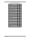
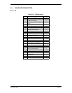
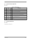
B.8 INVERTER BOARD CONNECTORS
B.8.1 J13
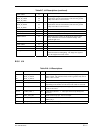
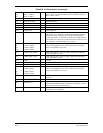
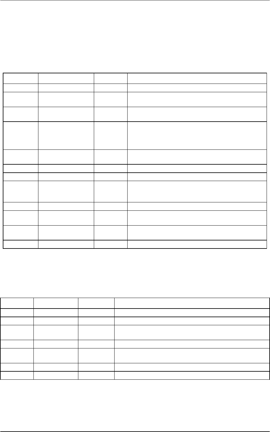
Table B-18. J13 Description
Pin # Pin Name I/O Description
1 12V I 11 to 14 V dc.
2 CCFT_TA_NOT I Cold Cathode Transmit A Not input. Occurs at 58.5 kHz
and is active low. Inverter is capacitor coupled.
3 CCFT_TB_NOT I Cold Cathode Transmit B Not input. Occurs at 58.5 kHz
and is active low. Inverter is capacitor coupled.
4 CCFT_CURRENT O Cold Cathode Fluorescent Tube Current is an output used
to measure the amount of current leaving the tubes.
Output is a half - wave rectified wave form of a 58.5 kHz
current source with a 1 k ohm in parallel.
5 HEATER_ON I Heater On Input that when high enables the heater.
Heater is capacitor coupled.
6VCC I
7 GND I Ground.
8 INVTR_ON I Inverter On input that when high enables the inverter fly-
back supply. Invertor on if Vin > 4.5 V and Invertor off if
Vin < 0.4 V.
9 Not used. I Not used.
10 INV_V_CTRL I Inverter Voltage control analog input. Valid ranges from 0
to 5 volts.
11 PWR_INVTR I Inverter Power provides fused power to the inverter
flyback.
12 PWR_HTR I Heater power provides fused power to the heater.
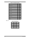
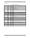
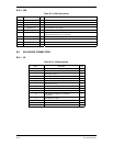
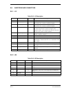
B.8.2 J26
Table B-19. J26 Description
Pin # Pin Name I/O Description
1 D O Bulb cathode.
2 Not used.
3 C I Bulb cathode. (May not be used if single bulb 463-00003-00 is
used.)
4 Not used.
5 B O Bulb cathode. (May not be used if single bulb 463-00003-00 is
used.)
6 Not used.
7 A I Bulb cathode.