


400 SERIES MAINTENANCE MANUAL Page 5-9
P/N 190-00140-05 Rev. C
5.5 ALIGNMENT
Board alignment is not recommended on any of the 400 Series units. Alignment is performed on
individual boards at the factory before being shipped as replacement items.
5.6 CALIBRATION
Calibration can be performed for the following:
COM Frequency
Frequency Spacing
SQ 250 – (the 25 kHz noise squelch)
SQ 833 – (the 8.33 kHz carrier squelch)
Sidetone Audio Output Level
MIC Gain
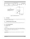
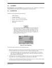
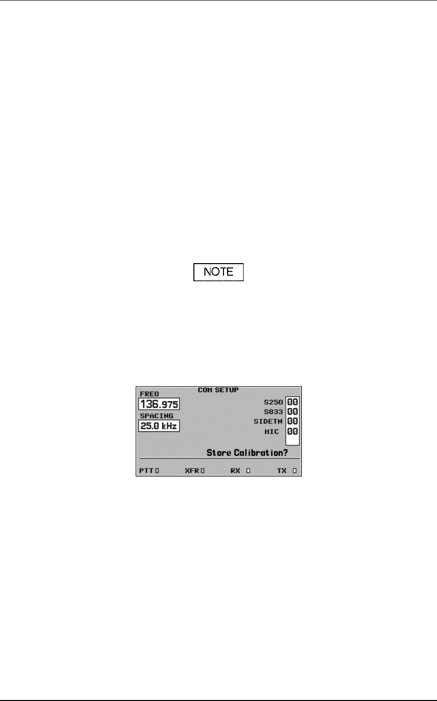
The unit must be placed in the configuration mode and the Com
Setup Page must be accessed in order to perform calibration
(Figure 5-2). Figure 5-2 shows the MIC field which is for –05
com boards and 105-00611-00 (16 watt) com boards only. For
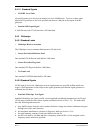
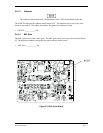
earlier versions of the board, the mic gain is adjusted via
potentiometer R558 (Figure 5-3).
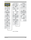
Figure 5-2. Com Setup Page
Follow these steps to put the unit in configuration mode:
1. With power applied to the aviation rack and the 400 Series unit turned off, press and hold the
ENT key and turn the unit on. Release the ENT key when the display activates.
After the database pages, the first page displayed is the MAIN ARINC 429 CONFIG
page. While in configuration mode, pages can be selected by ensuring the cursor is off
and rotating the small right knob.
2. To change data on the displayed configuration page, press the small right knob (CRSR) to
turn on the cursor. Turn the large right knob to switch between data fields.
3. Turn the large or small right knob to change a field that the cursor is on. Once you have made
the desired selection, press the ENT key to accept the entry.