


400 SERIES MAINTENANCE MANUAL Page B-7
P/N 190-00140-05 Rev. C
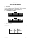
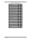
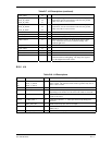
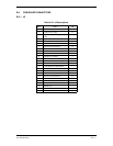
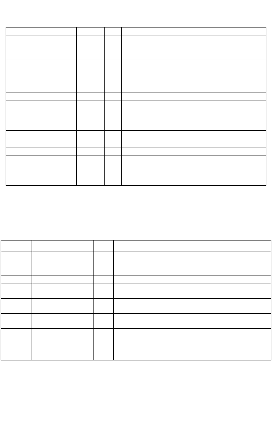
Table B-7. J12 Descriptions
(continued)
NOT USED 25
ROT_R_LRGA
ROT_R_LRGB
ROT_R_LRGC
64
26
27
I
I
I
Rotor Right Large A to C are the contacts of a single pole
triple throw switch. The common of the switch is ground.
Only one of the 3 is low at a time.
ROT_R_SMLA
ROT_R_SMLB
ROT_R_SMLC
61
62
63
I
I
I
Rotor Right Small A to C are the contacts of a single pole
triple throw switch. The common of the switch is ground.
Only one of the 3 is low at a time.
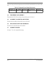
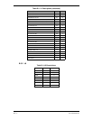
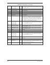
GND 28 O Ground.
ROT_R_SW 29 I Push switch on right rotary. Active low input.
UD1..UD8 38..45 O UPPER half display DATA output.
PHOTOCELL 51 I Photocell input is used to by the board to measure light
level. Photocells are resistive loads that change with
ambient light level.
5V_MISC 56
NOT USED 57 O
NOT USED 58 O
NOT USED 59 O
LED_COMMON 60 O Led common is a 4 kHz PWM output that controls bezel key
and nomenclature backlighting. The longer this signal is
low the brighter the LEDs will be.
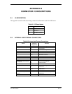
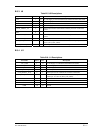
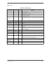
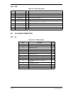
B.3.6 J14
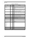
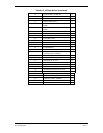
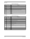
Table B-8. J14 Descriptions
Pin # Pin Name I/O Description
1
2
40
ROT_L_LRGC
ROT_L_LRGB
ROT_L_LRGA
I Rotor Left Large A to C are the contacts of a single pole triple
throw switch. The common of the switch is ground. Only one of
the 3 is low at a time.
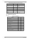
3..22 CARD_A01..A20 O Card Address 01 to 20.
23 CARD_RDN O Card Read Not. Output pulses low typically for 150 ns or 210 ns
depending on the number of wait states when cards are accessed.
24 CARD_WRN O Card Write Not. Output pulses low typically for 180 ns when
cards are accessed.
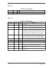
25..32 CARD_DL0..7 B1 Card Data Left Bit 0 .. 7. These pins float except during card
accesses.
33 POT_TOP_SW I Push switch on top pot. Active low input.
34 PWR_ON_2 I Power on number 2 contact. Powers unit on when connected to
PWR_ON_1.
35 POT_TOP_PWR O Provides Power to top pot.