


Page 5-28 400 SERIES MAINTENANCE MANUAL
Rev. C P/N 190-00140-05
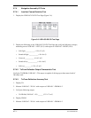
5.7.3.9 VOR Flag Sensitivity
A VOR/LOC +FLAG output voltage of greater than 260 mV
fully conceals the indicator flag (‘HIDE’) and a VOR/LOC
+FLAG output voltage of less than 125 mV fully reveals the
indicator flag (IN VIEW). This test requires a Precision Track
Selector or similar connected to the NAV OBS circuitry.
1. Apply a standard VOR test signal at 108.00 MHz at –103.5 dBm RF signal to the RF input.
2. Measure at the VOR/LOC +FLAG J6-3 and VOR/LOC -FLAG (VOR/LOC COMMON)
J6-4 outputs.
3. Verify the VOR/LOC +FLAG output is not less than 260 mV.
VOR/LOC +FLAG ________NLT 260 mV
5.7.3.10 LOC Flag Sensitivity
1. Apply a Standard Localizer Test Signal at 108.10 MHz at -103.5 dBM.
2. Measure at the VOR/LOC +FLAG J6-3 and VOR/LOC -FLAG (VOR/LOC COMMON)
J6-4 outputs.
3. Verify the VOR/LOC +FLAG output is not less than 260 mV.
VOR/LOC +FLAG Output ______ NLT 260 mV
4. Apply a LOC Standard Deviation Test Signal.
5. Lower the RF level such that it causes the course deviation output (VOR/LOC +LEFT) to be
less than 50% of standard deflection. 50% of standard deflection in LOC mode is 45 mV.
6. Verify the VOR/LOC +FLAG output is less than 125 mV (Flagged).
VOR/LOC +FLAG Output ______ < 125 mV
5.7.3.11 VOR/LOC Composite Test
1. Apply a standard VOR test signal to the RF input of the NAV receiver. Verify the VOR/LOC
COMPOSITE OUT is 0.5 r0.1 Vrms into a 10 k: load.
VOR/LOC COMPOSITE OUT ______ Vrms
2. Apply a standard localizer centering test signal to the RF input of the NAV receiver. Verify
the VOR/LOC COMPOSITE OUT is 0.333 r0.05 Vrms into a 10 k ohm load.
VOR/LOC COMPOSITE OUT ______ Vrms