


Page B-8 400 SERIES MAINTENANCE MANUAL
Rev. C P/N 190-00140-05
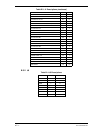
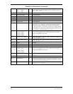
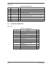
Table B-8. J14 Descriptions
(continued)
36
37
38
ROT_L_SMLC
ROT_L_SMLB
ROT_L_SMLA
I
I
I
Rotor Left Small A to C are the contacts of a single pole triple
throw switch. The common of the switch is ground. Only one of
the 3 is low at a time.
39 ROT_L_SW I Push switch on left rotary. Active low input.
41 POT_BOT_WPR I Bottom Pot Wiper.
42 CARD_A21 O Card Address 21.
43 GND O Ground.
44 VCC O
45 CARD_A22 O Card Address 22.
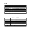
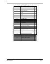
46 LFT_A22 Configured for a test mode enable input from the left data card.
This input is type I and allows a special down load board that fits
into the left slot to put the unit in test mode which then allows
writing to the flash. An alternate use of this pin is Address 22 for
the left data card. This may be used in the future to allow for card
size expansion. If in this mode the pin is type O.
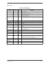
47
48
49
50
CARD_CSR3N
CARD_CSR2N
CARD_CSR1N
CARD_CSR0N
O Card chips select right 3 ..0 not. Outputs pulses low typically for
200 or 260, depending on wait states, when cards are accessed.
Only one should be low at a time.
51 CARD_DET_RGTN I Card detect right not. Active low input. Insertion of a data card
causes this input to be low.
52 CARD_DET_LFTN I Card detect left not. Active low input. Insertion of a data card
causes this input to be low.
53 GND O Ground.
54 VCC O
55 12V_REG O Regulated 12 V output.
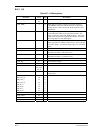
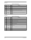
56
57
58
59
CARD_CSL3N
CARD_CSL2N
CARD_CSL1N
CARD_CSL0N
O Card chips select left 3 ..0 not. Outputs pulses low typically for
200 or 260, depending on wait states, when cards are accessed.
Only one should be low at a time.
60..67 CARD_DR7..0 B1 Card Data Right Bit 7..0. These pins float except during card
accesses.
68 POT_BOT_SW I
Push switch on bottom pot. Active low input.
69 PWR_ON_1 O
Power on number 1 contact. This input is connected to
AIRCRAFT POWER through approximately 3000 ohms. Powers
unit on when connected to PWR_ON_2.
70 POT_TOP_WRP I Top Pot Wiper. The source is the wiper of a 10 K ohm pot
connected to VCC and GND.