


400 SERIES MAINTENANCE MANUAL Page B-17
P/N 190-00140-05 Rev. C
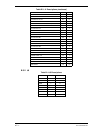
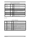
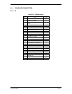
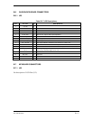
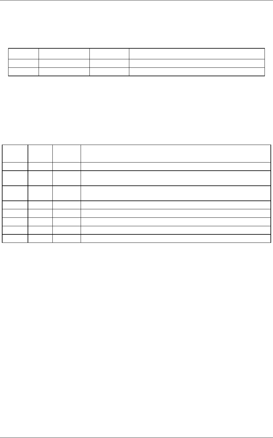
B.8.3 J27
Table B-20. J27 Description
Pin # Pin Name I/O DESCRIPTION
1 HEATER VIN O Heater high. The heater typical resistance is 16 ohms.
2 HEATER GND I Heater low.
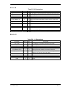
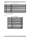
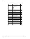
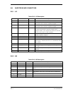
B.9 GPS MODULE CONNECTORS
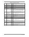
B.9.1 J101
Table B-21. J101 Descriptions
Pin # Pin
Name
I/O DESCRIPTION
TRAP 1 I 0 to 12 V dc 4 Khz PWM output used to position the GPS notch.
RSSI 2 O Relative Signal Strength Indicator input used to position GPS notch via the
TRAP output. Input impedance: AC > 1 K ohm.
BASEB
AND
3O
GND 4 0
CLK32 5 O 33 MHz clock.
GND 6 O Ground.
VCC 7 I
RSFW 8 I Logic high enables all power regulators.
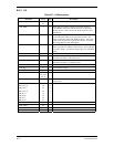
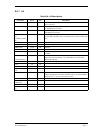
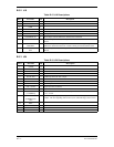
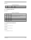
B. 10 INTERFACE BOARD CONNECTORS
B.10.1 J19
See Data Card Flex description (J14).
B.10.2 J20
J20 is the Left Data Card Connector.
B.10.3 J21
J21 is the Right data Card Connector.