


400 SERIES MAINTENANCE MANUAL Page B-5
P/N 190-00140-05 Rev. C
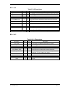
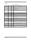
B.3.3 J9
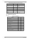
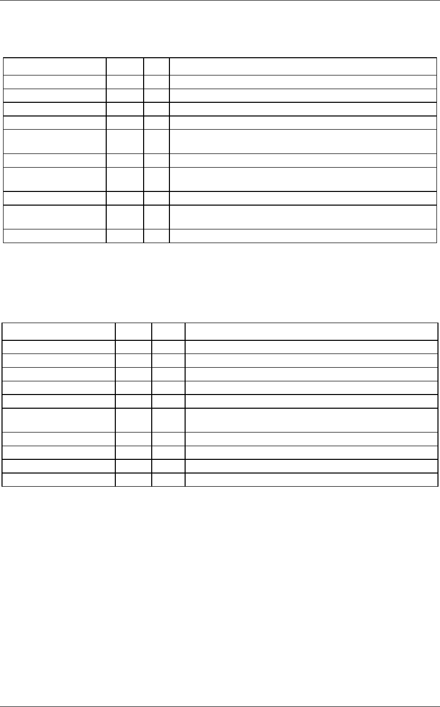
Table B-5. J9 Descriptions
Pin Name Pin # I/O Description
12V 1 O 12 volt Supply to NAV board and G/S board from Main CPU board.
5V_NAV 2 O +5 volt Supply to NAV board and G/S board from Main CPU board.
GND 3 O Ground.
-12V 4 O -12 volt Supply to NAV board and G/S board from Main CPU board.
VLOC_SERIAL_IN 5 O Serial output used to communicate with the processor on the NAV
board.
KEY 6 -
G/S_SERIAL_IN 7 O Serial output used to communicate with the processor on the G/S
board.
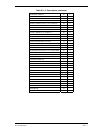
G/S_SERIAL_OUT 8 I Serial input used to communicate with the processor on G/S board.
NAV_VOL_CONTROL 9 O This is a dc output that is connected to the center tap of a pot. See
J14-41 (POT_BOT_WPR).
VLOC_SERIAL_OUT 10 I Serial input used to communicate with the processor on NAV board.
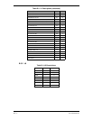
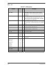
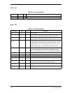
B.3.4 J11
Table B-6. J11 Descriptions
Pin Name Pin # I/O Description
12V_COM 1 O 12 volt Supply to COM board from Main CPU board.
-12V_COM 2 O -12 volt Supply to COM board from Main CPU board.
5V_COM 3 O +5 volt Supply to COM board from Main CPU board.
COM_SERIAL_IN 4 O Serial output used to communicate with the COM board.
COM_SERIAL_OUT 5 I Serial input used to communicate with the COM board.
COM_VOL_CONTROL 6 O This is a dc output that is connected to the center tap of the
volume pot. See J14-70 (POT_TOP_WPR).
Not used. 7
Not used. 8
GND 9 O Ground.
GND 10 O Ground.