


400 SERIES MAINTENANCE MANUAL Page 5-43
P/N 190-00140-05 Rev. C
5.7.6.4 Photocell
1. Turn the unit on in the test mode and verify brightness control is in photo mode, using the
main lighting page.
2. With photocell uncovered, ensure display and keyboard backlight LED brightness is proper
under normal conditions.
_____OK
3. Cover the photocell and verify display and keyboard backlight LED brightness decreases.
_____OK
5.7.6.5 Lighting Bus Input
If a lighting bus (any option other than PHOTO) is selected, and
the lighting bus control is turned to its minimum (daytime)
setting, the display brightness will default to tracking the unit’s
photocell.
The unit shall read a DC voltage from 0 to 20 volts with an accuracy of 5% or 0.5 volts
(whichever is greater) and a differential voltage of 5 Vrms at 400 Hz with and an accuracy of 5%
or 0.5 volts (whichever is greater).
For: LIGHTING BUS HI (J1-39).
LIGHTING BUS LO (J1-40).
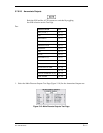
A. Lighting Bus AC
1. Using the Main Lighting Test Page, change the source to 5VAC in the display and key fields.
2. Input a square wave, 500 Hz, zero to +5 volt signal to pin J1-39 and J1-40.
A 500 Hz, +5 volt to –5 volt square wave from the IFR 2030 LF output can be used for
this test.
Use the Main Analog Inputs Test Page to monitor the test results.
3. Verify measured value is 5.00 volts r 0.25 VDC. To convert the display value to volts:
V = value x 0.03226.
Measured Value________ VDC
4. Vary the input signal amplitude, and verify the display lighting changes accordingly.
5. Cover the photocell and vary the input signal amplitude, verify the key lighting changes
accordingly.