Page 5-30 400 SERIES MAINTENANCE MANUAL
Rev. C P/N 190-00140-05
5.7.3.16 Course Deviation Accuracy Test
Apply a standard localizer deviation test signal, 90 Hz greater than 150Hz. Verify the deviation
measured at VOR/LOC +LEFT with respect to VOR/LOC +RIGHT (VOR/LOC COMMON) is
90 mV r9 mV.
_____OK
5.7.3.17 VOR OBS Bearing Accuracy
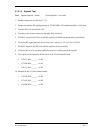
1. Apply a standard VOR test signal and a PTS or similar device at 60, 150, 240, and 330
degrees in course angle.
2. Monitor the bearing information on the unit display while in test mode.
The OBS bearing is consistent to within r2 degrees of the bearing setting. This output
requires an alignment. This alignment can be done on the unit level by using the unit test
page “MAIN CDI/OBS CONFIG”.
On this page, monitor the current measured angle using the “SELECTED COURSE” field
and calibrate the unit using the “Calibrate to 150?” field (do this after the bearing is selected
to 150 degrees). Note that the angle displayed is rounded to one tenth of one degree. Verify
no error more than 2 degrees.
Error______NGT 2
q
5.7.3.18 Selectivity
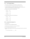
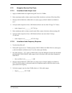
1. Apply a –93 dBm CW RF signal at a frequency of 110.0 MHz.
2. Measure IF AGC voltage and record as reference.
3. Increase the RF level by 6 dB to –87 dbM.
4. Adjust the RF frequency above the channel center frequency until the frequency is found that
produces an IF AGC voltage equal to the reference IF AGC voltage.
5. Record this (below) as the upper 6 dB bandwidth.
6. Find lower 6 dB bandwidth and record below. Increase RF level by 63 dB to –24 dbM.
7. Find upper 69 dbM bandwidth and record below. Find lower 69 dbM bandwidth and record
below.
Upper 6 dB BW______
t
110.0165 MHz
Lower 6 dB BW______
d
109.9835 MHz
Upper 69 dBm BW______
d
110.036 MHz
Lower 69 dBm BW______
t
109.964 MHz


