


Page 3-4 400 SERIES MAINTENANCE MANUAL
Rev. C P/N 190-00140-05
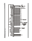
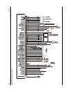
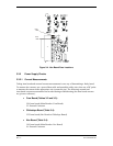
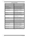
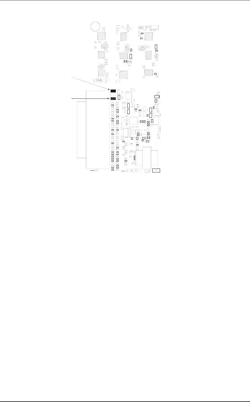
F501
1 AMP
J6
F502
1 AMP
Figure 3-4. Nav Board Fuse Locations
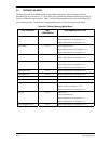
3.3.2 Power Supply Checks
3.3.2.1 Current Measurements
Taking intra-board and external current measurements is one way of determining a faulty board.
To measure the currents, use a spare ribbon cable and spread the cable wires, then use a DC probe
to measure the current in the appropriate wire (connector pin). The following external and
intra-board current measurements can be taken during troubleshooting (the intra-board currents
are given as reference):
x Com Board (Tables 3-2 and 3-3):
J26: Intra-board (Main Board to Com Board)
J2: External Connector
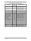
x Glideslope Board (Table 3-4):
J25: Intra-board (Nav Board to Glideslope Board)
x Nav Board (Table 3-4):
J10: Intra-board (Main Board to Nav Board)
J6: External Connector