


Page 3-10 400 SERIES MAINTENANCE MANUAL
Rev. C P/N 190-00140-05
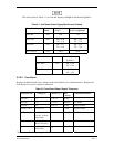
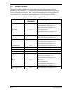
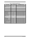
3.5 TESTING FAILURES
Another approach in troubleshooting is to perform testing on a unit according to the test
procedures given in Section 5. To save time, only perform the minimum amount of testing in
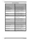
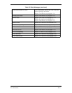
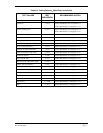
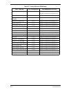
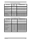
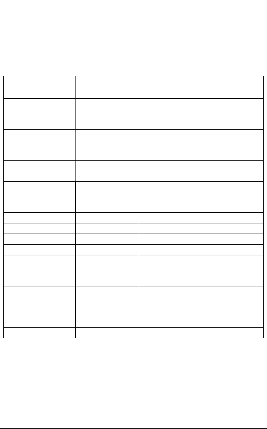
order to isolate the suspect board. Table 3-6 lists recommended actions based on failures that
occur during testing. Perform the recommended actions in the order given in the table.
Table 3-6. Testing FailuresMain Board
TEST FAILURE TEST
PARAGRAPH
RECOMMENDED ACTION
Push Button Response 5.7.6.1 Check Applicable Flex
Replace Map Board (see paragraph 4.5.5)
Replace Main Board (see paragraph 4.5.5)
Rotary Knobs 5.7.6.2 Check Applicable Flex
Replace Rotary Knob (see paragraph 4.5.2.1)
Replace Main Board (see paragraph 4.5.5)
Map I.D. and Data Card Test 5.7.6.3 Replace Map Board (see paragraph 4.5.5)
Replace Main Board (see paragraph 4.5.5)
Photocell 5.7.6.4 Check Applicable Flex
Replace Keyboard (see paragraph 4.5.2.1)
Replace Main Board (see paragraph 4.5.5)
Lighting Bus Input 5.7.6.5 Replace Main Board (see paragraph 4.5.5)
Lighting Bus AC 5.7.6.5A Replace Main Board (see paragraph 4.5.5)
Lighting Bus DC 5.7.6.5B Replace Main Board (see paragraph 4.5.5)
Memory Battery Voltage 5.7.6.6 Replace Memory Battery (see paragraph 4.7.1)
Display Pattern Test 5.7.6.7 Check Applicable Flex
Replace LCD (see paragraph 4.5.2.1)
Replace Main Board (see paragraph 4.5.5)
Fan Test 5.7.6.8 Replace Fan
Check Applicable Flex
Replace Map Board (see paragraph 4.5.5)
Replace Main Board (see paragraph 4.5.5)
Unit Configuration Test 5.7.6.9 Replace Main Board (see paragraph 4.5.5)