


Page 1-4 400 SERIES MAINTENANCE MANUAL
Rev. C P/N 190-00140-05
1.3 REPAIR PLAN
This manual is designed to allow the user to perform board-level repair. If necessary, the unit can
be returned to GARMIN for complete service work. Contact GARMIN at the address given on
Page A (inside cover) for further service information.
1.4 SPECIFICATIONS
Technical specifications for each unit are given in the 400 Series Installation Manual,
P/N 190-00140-02.
1.5 GENERAL DESCRIPTION
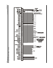
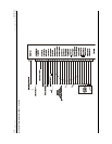
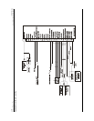
To help understand the general description, Appendix B lists all
external and internal I/O signal descriptions for each unit. Also,
see Figure 3-7 for a block diagram, which shows all of the
external and internal connectors for each board.
1.5.1 Main Board
The Main Board is the functional center of the unit. The Main Board communicates with all the
components of the unit, and provides the interface with the pilot and other avionics installed in
the aircraft.
The Main Board performs the following functions:
1. Communicates with all components of the unit.
2. Displays and controls interface with the pilot.
3. Displays the navigation database via a removable memory card for use by the
pilot/flight crew.
4. Area navigation functions using the determined position/velocity and stored
navigation data.
5. Interfaces with other flight instruments such as a moving map autopilot, CDI/HSI,
indicators, altitude encoder, fuel management system, and annunciators.