


400 SERIES MAINTENANCE MANUAL Page 4-3
P/N 190-00140-05 Rev. C
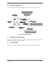
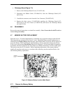
4.4 UNIT DESIGN
Each unit consists of a Main and Nav Chassis, CDU Assembly, and a Top Cover. The Main
Chassis has a Top and Underside Cavity which contains replaceable boards. The following is a
typical order of disassembly:
1. Remove the Top Cover.
2. Remove the CDU Assembly.
3. Disassemble the CDU Assembly.
4. Separate the Main and Nav Chassis.
5. Remove Defective Boards from the Main Chassis Top Cavity.
6. Remove Defective Boards from the Main Chassis Underside Cavity.
7. Remove Defective Boards from the Nav Chassis.
8. Replace the Memory Battery.
4.5 DISASSEMBLY PROCEDURE
Because each unit is very similar in design, only the GNS 430 disassembly procedure is given in
this section. The disassembly procedures are provided in modular sequence to enable disassembly
of the unit only to the extent required to perform repairs. Refer to Sections 6 and 7 for parts lists
and illustrations to help in the disassembly of the unit being repaired.
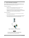
4.5.1 Remove the Top Cover (Figure 7-1)
Remove two screws (211-60234-06) and two screws (211-63234-10) and remove the Top
Cover (115-00218-00) (shields (253-00062-02) and (253-00062-01) will be removed
with the cover).
4.5.2 Remove the CDU Assembly (Figure 7-1)
1. Remove four screws (211-63234-10).
2. Disconnect the two flex cables (C and D) from the Main Board.
3. Disconnect wires from the Inverter Board (see Figure 7-2, P/N 012-00256-00).