


Page B-10 400 SERIES MAINTENANCE MANUAL
Rev. C P/N 190-00140-05
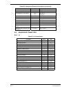
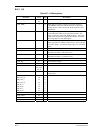
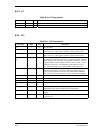
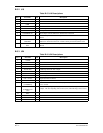
B.3.8 J17
Table B-10. J17 Descriptions
Pin Name Pin # I/O Description
FAN_HI 1 O Approx. 5 V.
FAN_LO 2 O Used to switch fan off and on.
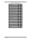
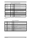
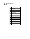
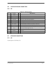
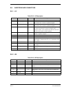
B.3.9 P13
Table B-11. P13 Descriptions
Pin Name Pin # I/O Description
12V 1 O 12 V dc output.
CCFT_TA_NOT 2 O Cold Cathode Transmit A Not logic level output. Occurs at 58.5 kHz
and is active low. This signal is capacitor coupled on the inverter.
CCFT_TB_NOT 3 O Cold Cathode Transmit B Not logic level output. Occurs at 58.5 kHz
and is active low. This signal is capacitor coupled on the inverter.
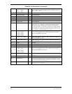
CCFT_CURRE
NT
4 I Cold Cathode Fluorescent Tube Current in an input used to measure
the amount of current leaving the tubes. Toggles from a DC resistance
of 100 K ohm to -12 VDC to an AC resistance of 10 Kohm. The AC
resistance mode is used to sample when the CCFT is on and is used to
sample the current level. The impedance level toggles at a rate of
71.13 Hz and the duty cycle is proportional to CCFT duty cycle.
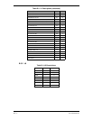
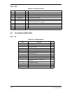
HEATER_ON 5 O Heater on that when high enables the heater. This signal is capacitor
coupled on the inverter. The signal is either: low (heater off), duty
cycle of 12.5% hi (heater on for 27.5 VDC AIRCRAFT POWER) or
duty cycle of 50% hi (heater on for 13.8 VDC AIRCRAFT POWER).
5V_MISC 6 O
GND 7 O Ground.
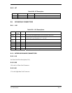
INVTR_ON 8 O Inverter On output that when high enables the inverter flyback supply.
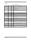
BULB_ON_STA
RT
9 O Not used.
INV_V_CTRL 10 O Inverter Voltage control analog output ranges from 0 to 5 volts. This
signal controls the voltage output of the inverter flyback.
PWR_INVTR 11 O Inverter Power provides fused AIRCRAFT POWER to the inverter
flyback.
PWR_HTR 12 O Heater power provides fused AIRCRAFT POWER to the heater found
on the inverter.