


Page 5-16 400 SERIES MAINTENANCE MANUAL
Rev. C P/N 190-00140-05
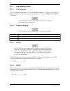
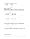
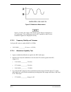
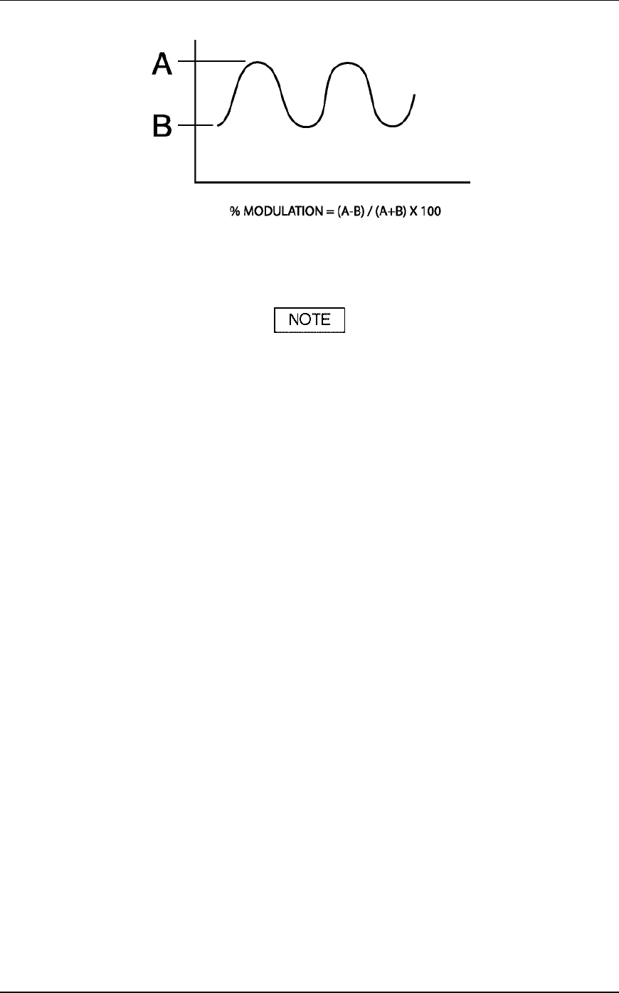
Figure 5-5. Modulation Measurement
Figure 5-5 shows the output of the Narda Crystal Detector displayed on
an oscilloscope. The oscilloscope must be DC coupled in order for the
modulation signal to be displayed correctly.
5.7.2.3 Frequency Stability and Tolerance
Verify the RF carrier is within 0.0005 % (5 PPM).
136.50 MHz _________ Hz (error < 683 Hz)
5.7.2.4 Modulation Capability Test
1. Apply a standard modulated test signal to the MIC audio input.
2. Measure and verify the modulation is not less than 70% and not greater than 90%
(Figure 5-5).
118.50 MHz _________ (70-90%)
127.50 MHz _________ (70-90%)
136.50 MHz _________ (70-90%)
3. To verify the MIC compressor has a minimum dynamic range of 20 dB, input a 2.75 Vrms
MIC signal and verify that the modulation percentage does not change more than 0.5 dB from
0.275 Vrms input.
127.00 MHz _________ change in dB