


400 SERIES MAINTENANCE MANUAL Page 3-15
P/N 190-00140-05 Rev. C
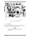
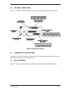
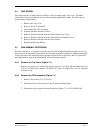
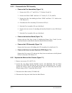
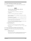
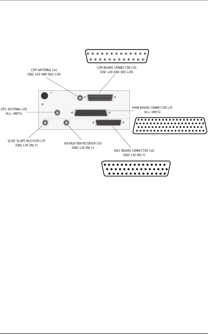
3.6 EXTERNAL CONNECTORS
Figure 3-6 shows the external connectors and their corresponding pin numbers for each unit.
123456789101112131415
161718192021
22
2324252627
2829
30
31
32
33343536373839
40
4142
43
44
1
2
34
5
67
89
10
11
12
14
15
16
17
18 19 20
21
22
23
24
25
13
1
2
3
4
5
6
7
8
9
10
11
12
13
14
15
16
17
18 19
20
21
22
23 24
25
26
27
28
29
30
31 32
33 34
35
36
37 38
39
40
41
42
43
44
45 46 47
48
49
51
52 53
54
55
56
57
58
59
60
61
62 63
64
65 66 67
68
69 70 71
72
73
74 75 76
77
78
50
Figure 3-6. External Connectors
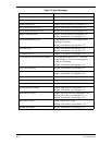
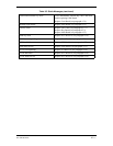
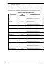
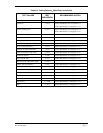
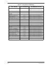
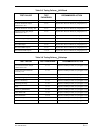
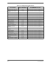
3.7 CONNECTOR I/O DESCRIPTIONS
Appendix B contains the pin names, numbers and a brief input/output description for the external
and internal connectors of each 400 Series unit.
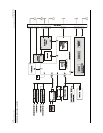
3.8 BLOCK DIAGRAM
Figure 3-7 shows a block diagram for the unit that can be used to help troubleshoot the unit.