


Page 4-6 400 SERIES MAINTENANCE MANUAL
Rev. C P/N 190-00140-05
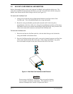
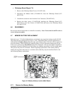
x GPS Module (Figure 7-2)
1. Disconnect the Ribbon Cable from the GPS Module (011-00474-XX).
2. Remove screw (211-60234-11) attaching the Map Board (012-00296-00) to
the Main Chassis (125-00034-01). Remove 3 of 5 screws (211-63234-10)
attaching GPS Module (011-00474-XX) to the Main Chassis (125-00034-01)
and remove the GPS Module.
x Main Board (Figure 7-2)
1. Remove the CDU Assembly (paragraph 4.5.2).
2. Remove the Map Board (paragraph 4.5.5).
3. Remove GPS Module (paragraph 4.5.5).
4. Remove the two screws (211-63234-10) attaching the 78-pin connector to the
Main Chassis (125-00034-01).
5. Remove the five screws (211-60234-06) attaching the Main Board (012-
00347-XX) to the Main Chassis (125-00034-01).
4.5.6 Remove Faulty Boards from the Nav Chassis
x Nav Receiver Board (Figure 7-3)
To access the bottom sub-assemblies, separate the Main Chassis from the Nav
Chassis according to the instructions given in paragraph 4.5.3.
1. Remove the Module Cover (115-00214-00). Disconnect the Ribbon Cable
(325-00063-01) from the Nav Receiver Board (012-00195-XX).
2. Remove the RF Fence Cover (115-00213-00).
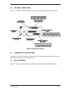
3. Unsolder the wire from the Coax Connector (330-00070-03).
4. Remove five screws (211-60234-04) attaching Nav Receiver Board
(012-00195-XX) to Nav Chassis (125-00035-00).
5. Remove the two screws (211-63234-10) attaching the 44-pin connector to
Nav Chassis (125-00035-00) and remove the Nav Receiver Board
(012-00195-XX).