


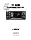

Page iv 400 SERIES MAINTENANCE MANUAL
P/N 190-00140-05 Rev. C
SECTION 3
TROUBLESHOOTING
Paragraph Page
3.1 TROUBLESHOOTING EQUIPMENT .....................................................................3-1
3.2 TROUBLESHOOTING ORDER..............................................................................3-1
3.3 TROUBLESHOOTING PROCEDURES .................................................................3-2
3.3.1 Fuses...............................................................................................................3-2
3.3.2 Power Supply Checks .....................................................................................3-4
3.3.2.1 Current Measurements....................................................................................3-4
3.3.2.2 Com Board .....................................................................................................3-5
3.3.2.3 Glideslope Board.............................................................................................3-6
3.3.2.4 Nav Board .......................................................................................................3-6
3.3.3 Processor Clock Check...................................................................................3-6
3.3.3.1 Internal Clock CheckMain Processor...........................................................3-6
3.3.3.2 Internal Clock CheckGPS Processor...........................................................3-6
3.4 STATIC MESSAGES..............................................................................................3-7
3.5 TESTING FAILURES............................................................................................3-10
3.6 EXTERNAL CONNECTORS ................................................................................3-15
3.7 CONNECTOR I/O DESCRIPTIONS.....................................................................3-15
3.8 BLOCK DIAGRAM................................................................................................3-15
SECTION 4
DISASSEMBLY AND ASSEMBLY
Paragraph Page
4.1 INTRODUCTION...................................................................................................4-1
4.2 REQUIRED TOOLS ..............................................................................................4-1
4.3 NAV DATA CARD REMOVAL AND INSERTION..................................................4-2
4.4 UNIT DESIGN ......................................................................................................4-3
4.5 DISASSEMBLY PROCEDURE.............................................................................4-3
4.5.1 Remove the Top Cover ...................................................................................4-3
4.5.2 Remove the CDU Assembly ...........................................................................4-3
4.5.2.1 Disassemble the CDU Assembly ...................................................................4-4
4.5.3 Separate the Main and Nav Chassis...............................................................4-4
4.5.4 Remove Faulty Boards from the Main Chassis Top Cavity ............................4-5
4.5.5 Remove Faulty Boards from the Main Chassis Underside Cavity...................4-5
4.5.6 Remove Faulty Boards from the Nav Chassis ...............................................4-6
4.6 REASSEMBLY......................................................................................................4-7
4.7 MEMORY BATTERY REPLACEMENT.................................................................4-7
4.7.1 Remove the Memory Battery...........................................................................4-8