


Page 5-2 400 SERIES MAINTENANCE MANUAL
Rev. C P/N 190-00140-05
Avionics Signal GeneratorIFR or Marconi 2030 w/options one and six.
BF Goodrich Precision Track Selector
Digital Voltmeter—HP 34401A
GPS Antenna—GARMIN GA56 (P/N 010-10040-01)
Power Supply capable of 10-33 Volts @ 10 Amps—HP 6267B
Radio Test Set—HP 8920A
Modulation AnalyzerHP 8901
The RF Signal Generator must have at least a 0.2 parts per
million (ppm) accuracy and the phase noise must be at least
–104.5 dBc/Hz @ 7.37 KHz offset for measuring the 8.33 kHz
receiver selectivity.
The following equipment (or suitable substitutes) can be used in place of the radio test set:
50 Watt, 30 dB Attenuator for the output of the Bird Wattmeter
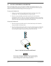
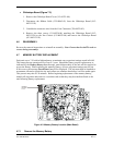
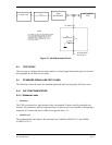
40 dB Attenuator Circuit—Shown in Figure 5-1
6 dB Attenuator CircuitMini-Circuits Model CAT-6
Crystal Detector—Narda 503-03
Frequency Counter—HP53131A
Oscilloscope—Tektronix TDS 3012
RF Signal Generator—IFR or Marconi 2030 with options 1 and 6.
RF Wattmeter—Bird 4431 with element 25C
Audio Distortion Analyzer—HP 8903B